Power Supply Control Device

a power supply control and power supply technology, applied in the direction of battery/fuel cell control arrangement, coupling device connection, instruments, etc., can solve the problems of wasteful voltage supply and inability to lower the voltage, and achieve the effect of reducing wasteful power supply, reducing power consumption, and preserving power

Inactive Publication Date: 2013-09-26
YAZAKI CORP
View PDF6 Cites 6 Cited by
  • Summary
  • Abstract
  • Description
  • Claims
  • Application Information

AI Technical Summary

Benefits of technology

The invention is a power supply control device that conserves power and increases the service life of a load by eliminating wasteful feed of power. It includes a switch element, an on-off control section, and a voltage detecting section that detects a voltage supplied from a power supply to a load. The on-off control section controls to turn on and off the switch element intermittently and shortens the duty ratio of an on-time period of the switch element in response to an increase in the supplied voltage detected by the voltage detecting section. This results in a suppression of power to be constant as the supplied voltage is increased, avoiding the wasteful power. The invention also reduces power consumption and fuel consumption when using an alternator or DC / DC converter, respectively, improving the efficiency of the power generation and battery usage.

Problems solved by technology

Therefore, when a voltage of the rated voltage or higher is supplied to the load 3, a wasteful voltage is supplied.
However, it is impossible to lower the voltage, which is output from the alternator 4 and the like, to the rated voltage.

Method used


Image

  • Power Supply Control Device
  • Power Supply Control Device
  • Power Supply Control Device

Examples


Embodiment Construction

First Illustrative Embodiment

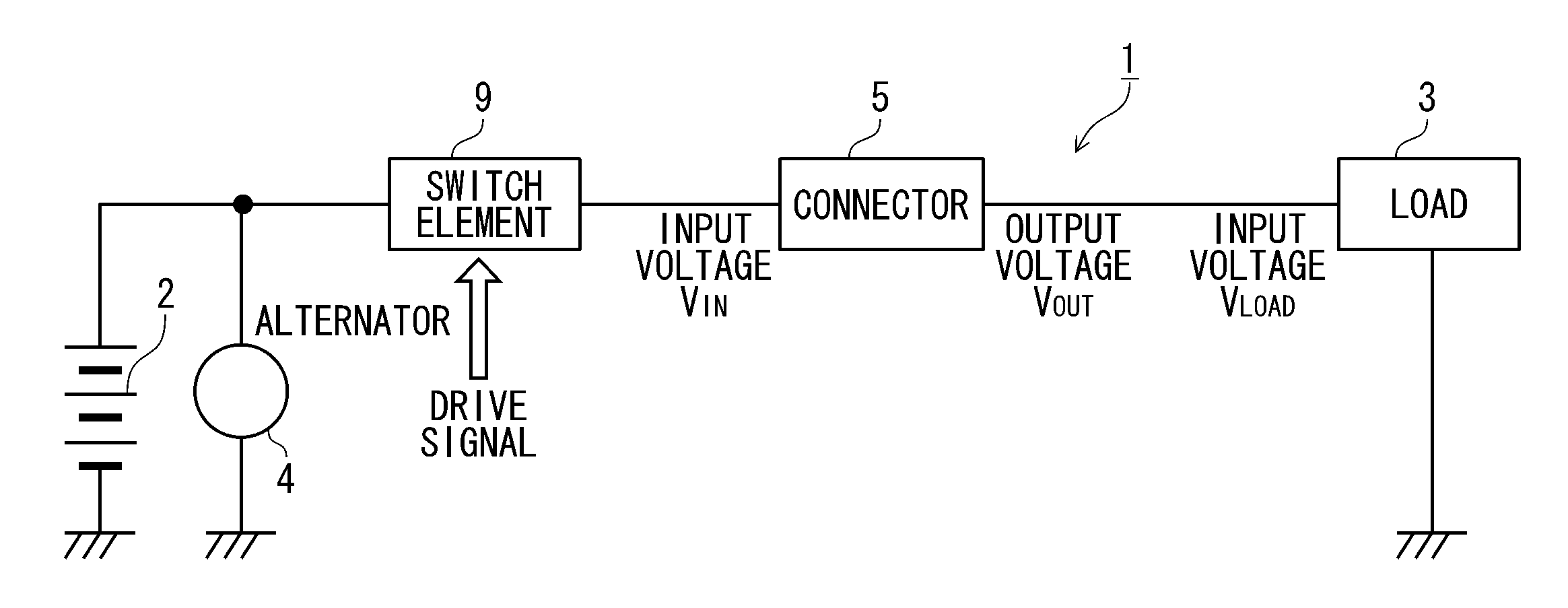
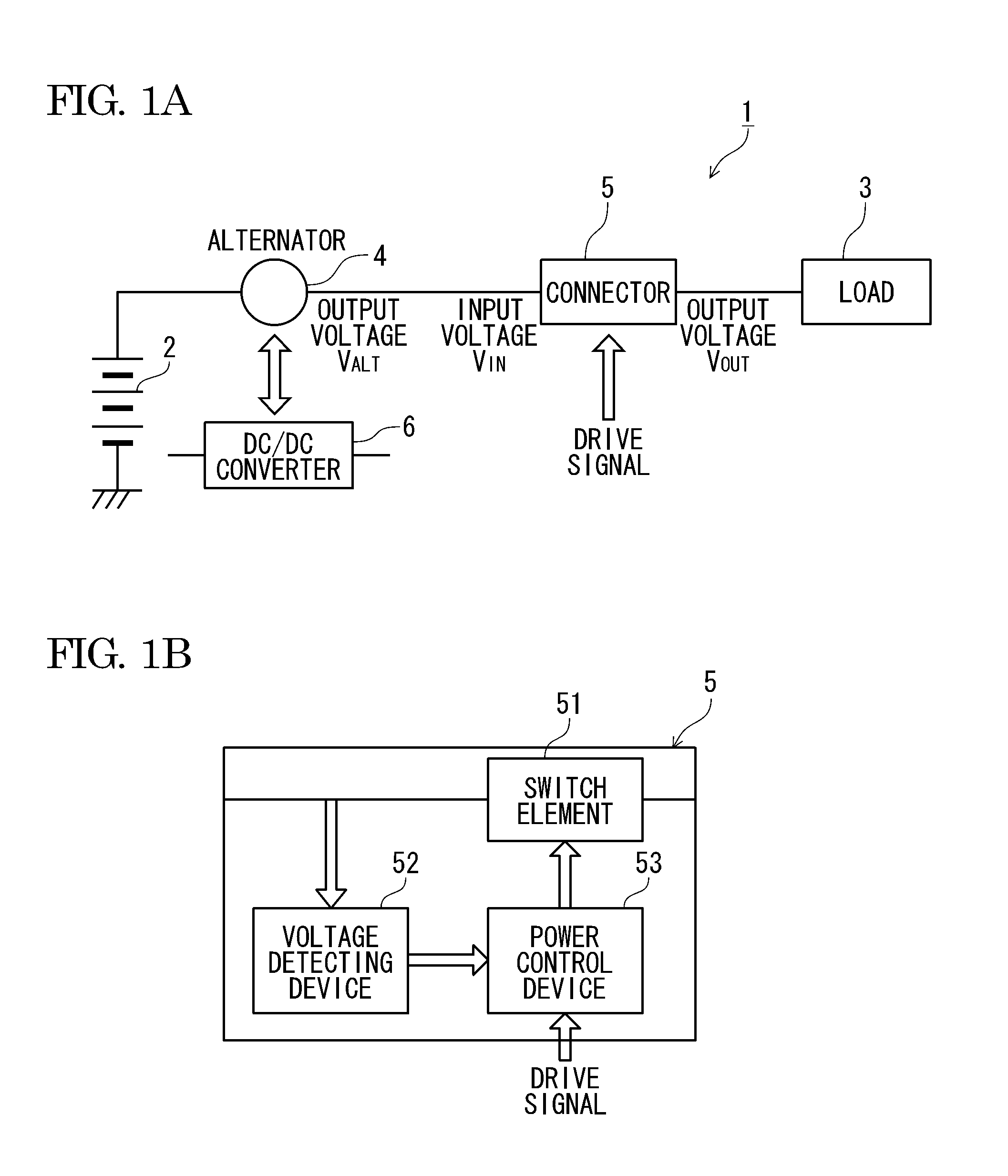
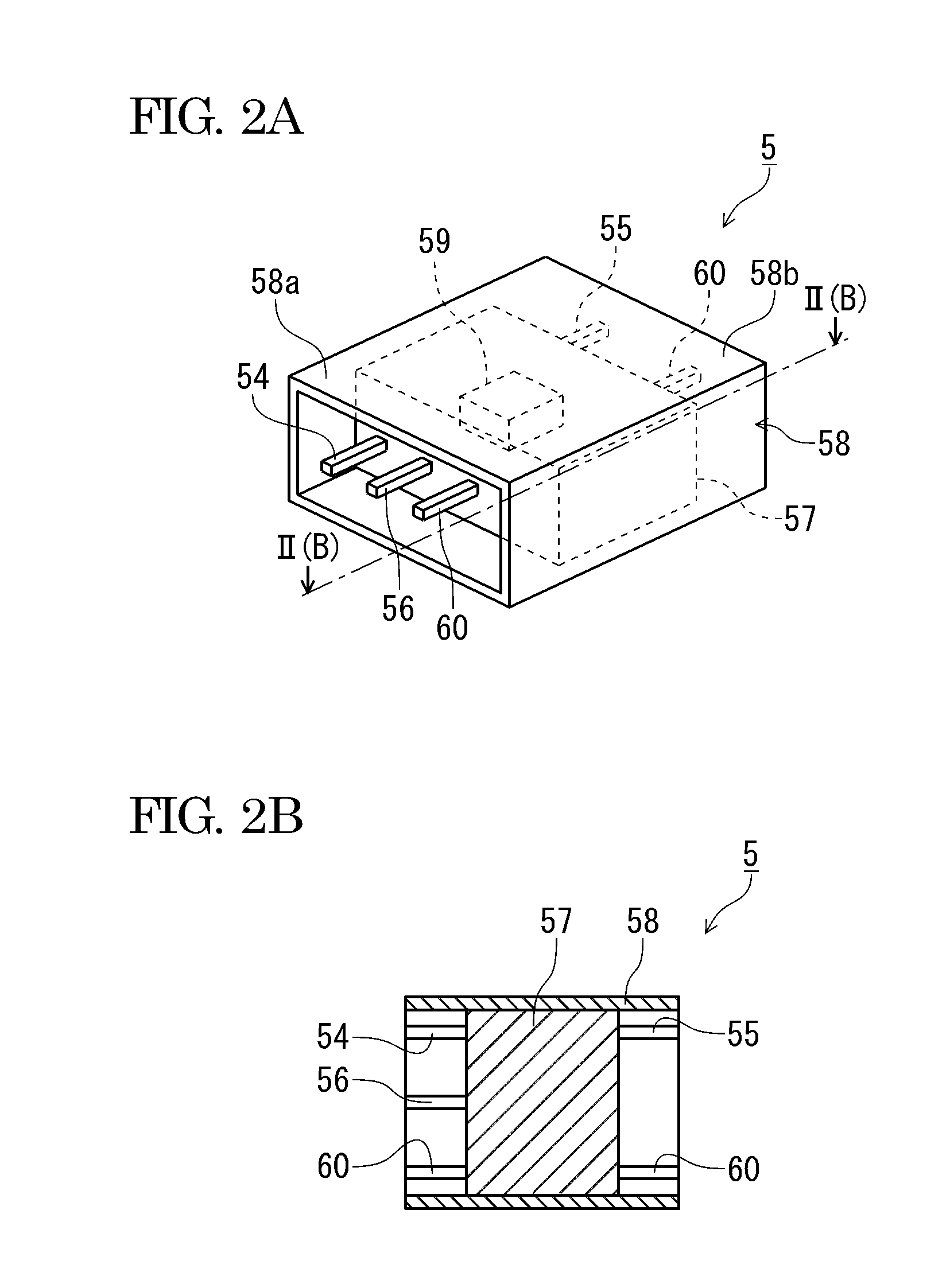
[0031]Hereinafter, the power supply control device of the invention will be described with reference to the drawings. FIG. 1A is a circuit diagram showing a first illustrative embodiment of a power supply device having incorporated a connector serving as the power supply control device of the invention and FIG. 1B is a detailed circuit diagram of the connector shown in FIG. 1A. FIG. 2A is a perspective view showing an outward appearance of the connector shown in FIG. 1B and FIG. 2B is a sectional view taken along a line II(B)-II(B) of FIG. 2A.

[0032]The power supply device 1 is mounted on an ICEV (Internal Combustion Engine Vehicle). As shown in FIGS. 1A and 1B, the power supply device 1 has a battery 2 serving as a power supply, a load 3 that operates as power from the battery 2 and the like is fed thereto, an alternator 4 that is provided between the battery 2 and the load 3, a power supply control device that controls power feeding to the load 3 and a ...


PUM


Abstract

A power supply control device includes a switch element that is provided between a power supply and a load, an on-off control section that controls to turn on and off the switch element, and a voltage detecting section that detects a voltage supplied from the power supply to the load. The on-off control section controls to turn on the switch element intermittently and shortens a duty ratio of an on-time period of the switch element in accordance with an increase of the supplied voltage detected by the voltage detecting section.

Description

CROSS REFERENCE TO RELATED APPLICATION[0001]This application is a continuation of PCT application No. PCT / JP2011 / 076309, which was filed on Nov. 15, 2011 based on Japanese Patent Application (No. 2010-258209) filed on Nov. 18, 2010, the contents of which are incorporated herein by reference. Also, all the references cited herein are incorporated as a whole.BACKGROUND[0002]1. Technical Field[0003]The invention relates to a power supply control device.[0004]2. Background Art[0005]A vehicle such as automobile is mounted with a power supply device for feeding power to each load. For example, JP-A-2010-233366 discloses a power supply device.SUMMARY[0006]FIG. 11 shows an example of a power supply device of the related art. As shown in FIG. 11, a power supply device 1 has a switch element 51 that is provided between a battery 2 serving as a power supply and a load 3 and a control device (not shown) serving as an on-off control unit that turns on-off the switch element 51.[0007]As the switc...

Claims


Application Information

Patent Timeline
Patent Type & Authority Applications(United States)
IPC IPC(8): H02M3/04
CPCH02J7/1438Y02T10/7005H02M3/04B60L1/00Y02T10/7216B60L15/08B60L2210/10B60L2240/547Y02T10/7066B60L11/1868H01R13/6666H02M3/156B60L58/20Y02T10/70Y02T10/64Y02T10/72H02M1/0022
Inventor SATAKE, SHUUJIKANAZAWA, AKIYOSHI
Owner YAZAKI CORP
Why Eureka
Try Eureka