
Method for operating a drive train

Inactive Publication Date: 2013-03-07
ZF FRIEDRICHSHAFEN AG
View PDF2 Cites 14 Cited by
  • Summary
  • Abstract
  • Description
  • Claims
  • Application Information

AI Technical Summary

Benefits of technology

The invention proposes a way to use the inertial mass of an electric machine to synchronize a transmission shaft that needs to be synchronized. This makes it possible to dispense with synchronizer rings, which simplifies the structure of the transmission and makes shifting faster and more smooth.

Problems solved by technology

This can result in relatively long shifting times.

Method used


Image

  • Method for operating a drive train
  • Method for operating a drive train
  • Method for operating a drive train

Examples


Embodiment Construction

[0016]The present invention concerns a method for operating a drive-train of a motor vehicle, namely a hybrid vehicle.

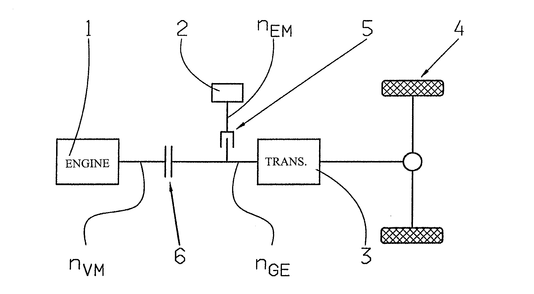
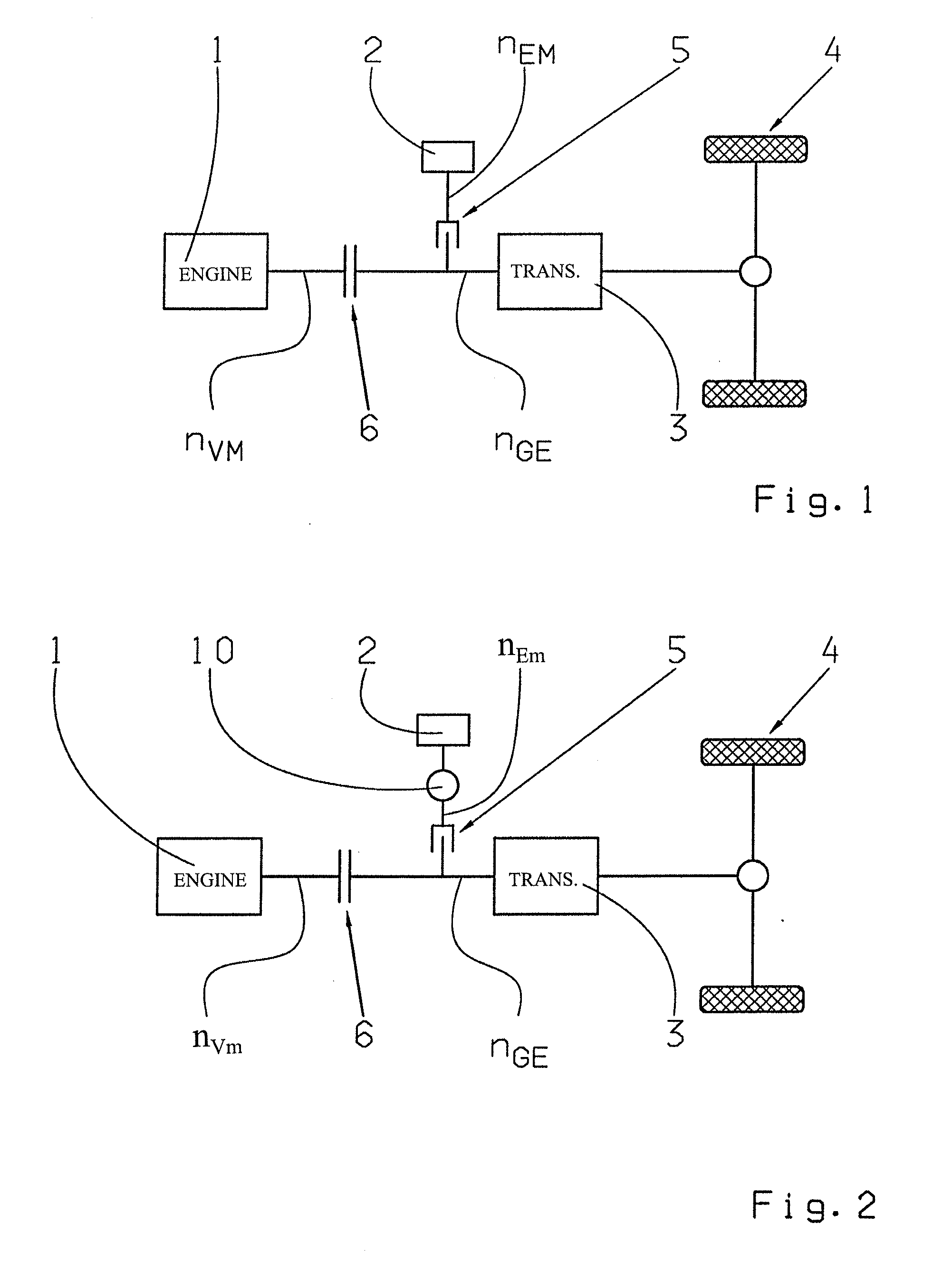
[0017]FIG. 1 shows a first drive-train layout of a hybrid vehicle, in which the method according to the invention can be used. The drive-train in FIG. 1 comprises an internal combustion engine 1, an electric machine 2, an automated variable-speed transmission 3 and a drive output 4, the automated transmission 3 being connected between the internal combustion engine 1 and the drive output 4. Likewise, the automated transmission 3 is connected between the electric machine 2 and the output 4.

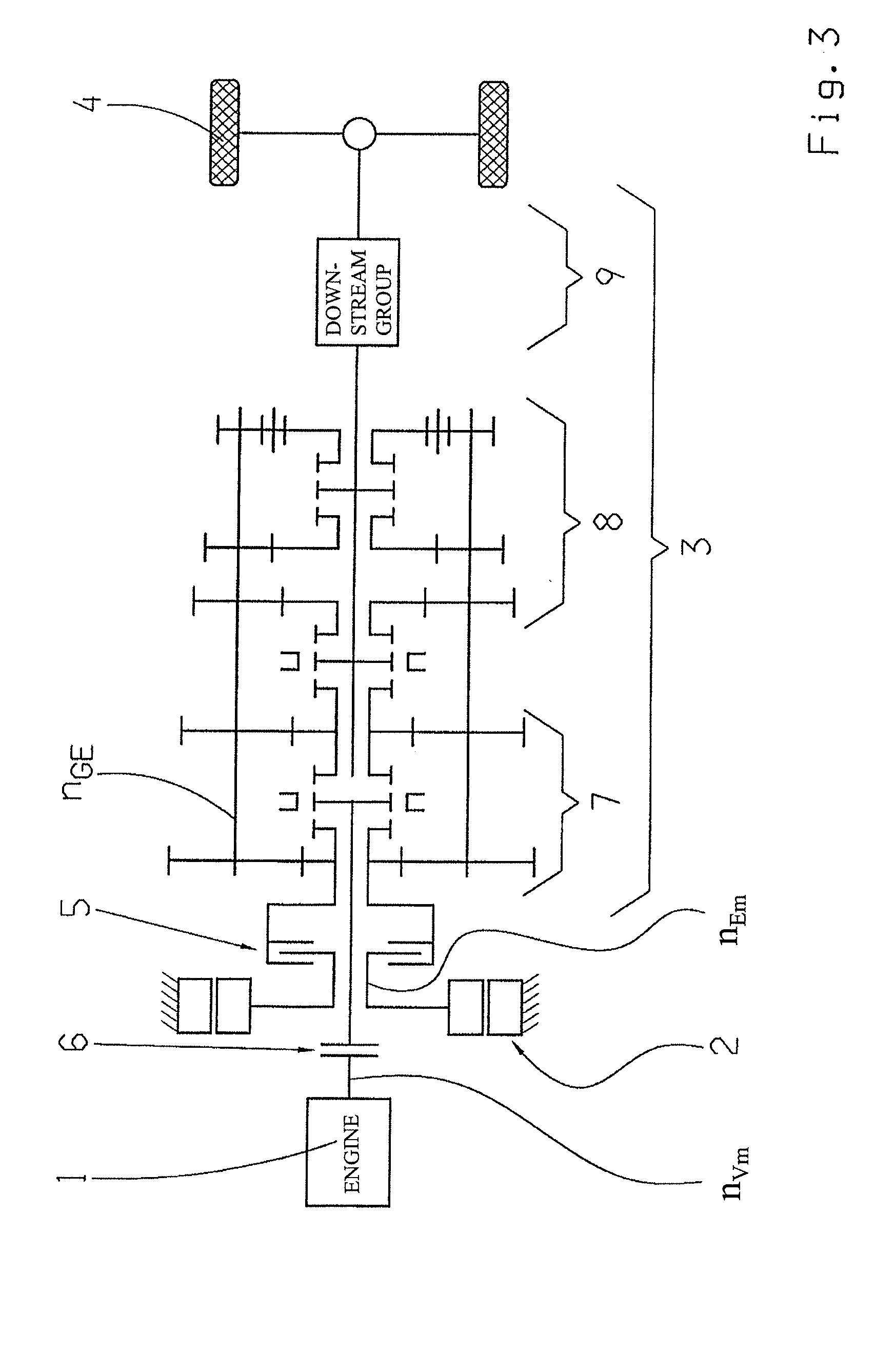
[0018]In FIG. 1 both the internal combustion engine 1 and the electric machine 2 of the drive-train engage with a transmission input shaft of the automated transmission 3. As shown in FIG. 1, the electric machine 2 engages with the transmission input shaft of the automated transmission 3 by way of a friction clutch 5. The internal combustion engine 1 engages with the transmission in...


PUM


Abstract

A method of operating a drive-train having a drive aggregate comprising an electric machine and internal combustion engine. An automated variable-speed transmission is connected between the engine and a drive output. The electric machine couples, via a friction clutch, a shaft of the transmission. Gearshifts are carried out in the transmission with an interruption of the drive torque provided by the drive aggregate in such manner that first the drive torque, provided at the output, is reduced to zero, then the actual gearshift is carried out, and then the drive torque, at the output, is again built up. To accomplish the gearshift, after disengaging a current gear and before engaging a target gear, the shaft of the transmission, which couples the electric machine via the friction clutch, is synchronized utilizing the inertial mass of the electric machine.

Description

[0001]This application is a National Stage completion of PCT / EP2011 / 055160 filed Apr. 4, 2011, which claims priority from German patent application serial no. 10 2010 028 936.1 filed May 12, 2010.FIELD OF THE INVENTION[0002]The invention concerns a method for operating a drive-train of a motor vehicle.BACKGROUND OF THE INVENTION[0003]The main components of a drive-train of a motor vehicle are a drive aggregate and a transmission. The transmission converts rotational speeds and torques and thereby transmits a traction force provided by the drive aggregate to a drive output of the drive-train. The present invention concerns a method for operating a drive-train of a hybrid vehicle whose drive aggregate comprises at least an electric machine and an internal combustion engine. Between the internal combustion engine and a drive output is connected an automated variable-speed transmission. The electric machine is coupled by a friction clutch to a shaft of the automated transmission.[0004]I...

Claims


Application Information

Patent Timeline
IPC IPC(8): B60W10/08B60W10/111B60W30/19
CPCB60K2006/4825B60W10/08B60W10/111B60W20/00B60W30/19B60W2510/088Y10T477/26F16H3/097F16H61/0403F16H61/682F16H2061/0422F16H2061/0433Y02T10/6252F16H3/095Y02T10/62B60W20/10
Inventor KALTENBACH, JOHANNES
Owner ZF FRIEDRICHSHAFEN AG
Learn More