
Embolic material excision trapping device

a trapping device and embolic material technology, applied in the field of embolic material excision trapping device, can solve the problems of short time, short supply of oxygen and nutrition to brain cells, loss of function of dead parts, etc., and achieve the effect of efficiently removing embolic materials and minimizing adverse effects on patients

Inactive Publication Date: 2013-02-28
ACCESS POINT
View PDF6 Cites 32 Cited by
  • Summary
  • Abstract
  • Description
  • Claims
  • Application Information

AI Technical Summary

Benefits of technology

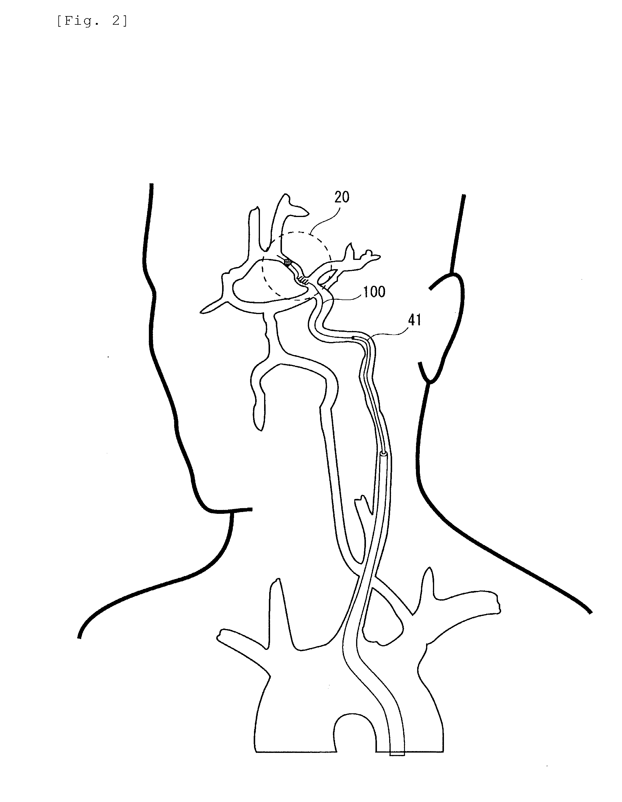
The invention is a device that can remove blockages in blood vessels without stopping the flow of blood. It uses a balloon to keep the blood vessels open while the blockage is being cleared. This minimizes the harmful effects on the patient and ensures that the blood flow is not blocked for too long. The device has two parts: a coil that removes the blockage and a filter that catches any loose pieces of the blockage that might escape from the coil. This setup improves the effectiveness of the treatment.

Problems solved by technology

When the blood flow to the brain is blocked by the embolic material, supplies of oxygen and nutrition to brain cells are interrupted, and the brain cells become necrotic in a short time.
Unless the normal blood flow is secured immediately, brain tissue will die, the function of the dead portion is lost, and the life threatening risk to the patient becomes high.
However, the cerebral embolic material dissolving remedy or medication has a possibility that the embolic material cannot be dissolved completely.
Further, such a case may occur that the transferred embolic material flows into the peripheral side of the lesion to block the blood flow again, and that a severe complication thereby occurs.

Method used


Image

  • Embolic material excision trapping device
  • Embolic material excision trapping device
  • Embolic material excision trapping device

Examples


example 1

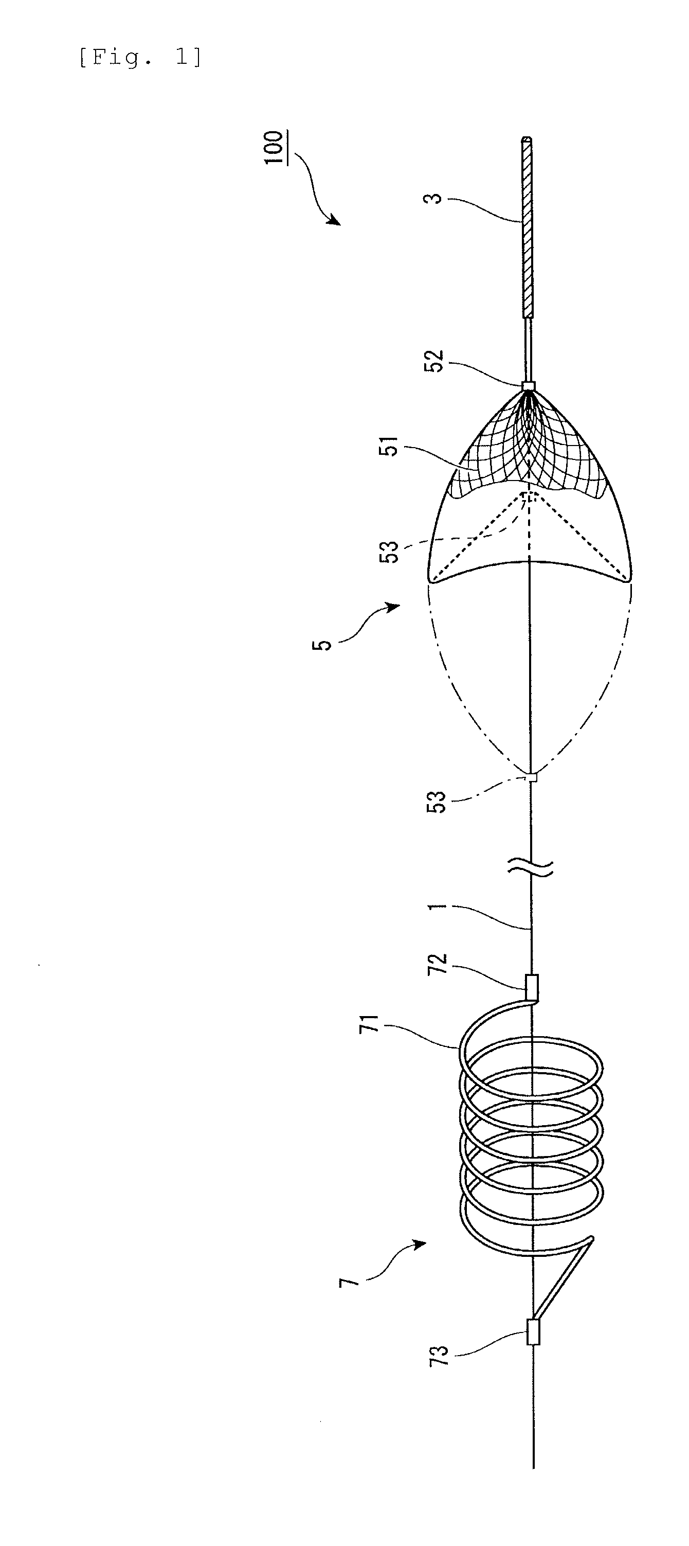
[0036]FIG. 1 is an entire schematic view of an embolic material excision trapping device according to Embodiment 1 of the invention. As shown in the figure, the embolic material excision trapping device 100 is formed of a shaft 1, and a guide portion 3, a basket filter 5, and an excising coil 7 provided in the shaft 1. The guide portion 3 is first provided at the front end (distal end) of the shaft 1, and then, the basket filter 5 and excising coil 7 are disposed in this order in the axis direction toward the base end (proximal end) of the shaft 1.

[0037]The shaft 1 is formed of a long wire (screw wire), and inserted into a catheter described later. The shaft 1 is movable in the axis direction inside the catheter by operating the base end. Suitable as a material of the shaft 1 is metal such as nickel-titanium alloys, stainless steel, titanium and the like.

[0038]At the front end (distal end) of the shaft 1 is provided the guide portion 3 having flexibility. The guide portion 3 is form...

example 2

[0055]This Embodiment describes an example of using a parachute type basket filter substituting for the parasol type basket filter of Embodiment 1. FIG. 6 is an entire schematic view of an embolic material excision trapping device according to Embodiment 2 of the invention. Further, FIG. 7 is a schematic view showing an aspect in using the embolic material excision trapping device. In addition, the same parts as in Embodiment 1 are assigned the same reference numerals to omit specific descriptions thereof.

[0056]In the embolic material excision trapping device 200 of this Embodiment, a basket filter 150 is formed of mesh woven of a plurality of metal wires 151 having elasticity or shape memory properties. A shape of the filter 150 is a substantially elliptical form as shown in FIG. 7, the mesh portion occupies almost a half in the ellipse, and thus, the filter has a parachute-like shape such that support wires 155 support the semi-elliptical mesh portion. The mesh portion correspondi...

example 3

[0062]This Embodiment describes an example of using an excising coil formed of a plurality of wires substituting for the excising coil formed of a single wire of Embodiment 1. FIG. 8 is an entire schematic view of an embolic material excision trapping device according to Embodiment 3 of the invention. Further, FIG. 9 is a schematic view showing an aspect in using the embolic material excision trapping device. In addition, the same parts as in Embodiment 1 are assigned the same reference numerals to omit specific descriptions thereof.

[0063]In the embolic material excision trapping device 300 of this Embodiment, an excising coil 170 is formed of a plurality of wires 171 having elasticity or shape memory properties. The wires 171 maintain a spiral shape as shown in FIG. 8 by the elasticity or shape memory properties in a free state. It is preferable to use three to five wires as the plurality of wires 171 (shown herein is the example of using three wires, 171A, 171B and 171C.) The diam...


PUM


Abstract

To provide an embolic material excision trapping device capable of excising an embolic material in an arteriole or vessel without blocking the blood flow, and further, trapping the material with reliability. A device for removing an embolic material in a lumen in a living body has a long shaft member 1 having a front end and a base end and sending the front end to a distal end of the lumen, a filter member 5 which is provided on the front-end side of the shaft member 1, and contracts linearly inside a catheter for carrying the device while expanding when released into the lumen from the catheter, and a coil member 7 which is provided in the shaft member 1 on the side closer to the base-end side than the filter member 5, and contracts linearly inside the catheter while expanding spirally when released into the lumen from the catheter, where the coil member 7 destroys and traps an embolic material in the lumen, and the filter member 5 traps an liberated piece of the embolic material.

Description

TECHNICAL FIELD[0001]The present invention relates to an embolic material excision trapping device to excise and trap an embolic material such as a thrombus and the like in a lumen in a living body.BACKGROUND ART[0002]Cerebral infarction is a disease occurring when an embolic material (such as a thrombus, fatty embolic material, tumor embolic material and the like) enters an artery of a brain, narrows the artery and blocks the blood flow, and cerebral ischemia arises. When the blood flow to the brain is blocked by the embolic material, supplies of oxygen and nutrition to brain cells are interrupted, and the brain cells become necrotic in a short time. Therefore, it is important to secure the normal blood flow promptly in the early stage of the onset of cerebral infarction. Unless the normal blood flow is secured immediately, brain tissue will die, the function of the dead portion is lost, and the life threatening risk to the patient becomes high.[0003]As treatment for cerebral infar...

Claims


Application Information

Patent Timeline
IPC IPC(8): A61F2/01
CPCA61B17/221A61B17/3207A61B2017/00867A61B2017/320733A61B2017/22038A61B2017/2212A61B2017/2217A61B2017/22034A61B2017/320716A61F2/013A61F2002/016A61F2230/0008A61F2230/0067A61F2/014A61B17/1214A61F2/90
Inventor HOCKING, GORDON DONALDCHENG, ZHENGHUI
Owner ACCESS POINT
Learn More