Method and structure for suppressing resonance in an Anti-shake lens focusing module
a technology of anti-shake lens and resonance, which is applied in the field of method and structure for suppressing resonance in anti-shake lens focusing modules, can solve the problems that the whole anti-shake lens focusing module might become inactive or abnormal, and achieve the effects of suppressing resonance, suppressing resonance, and suppressing resonan
- Summary
- Abstract
- Description
- Claims
- Application Information
AI Technical Summary
Benefits of technology
Problems solved by technology
Method used
Image

Examples
first embodiment
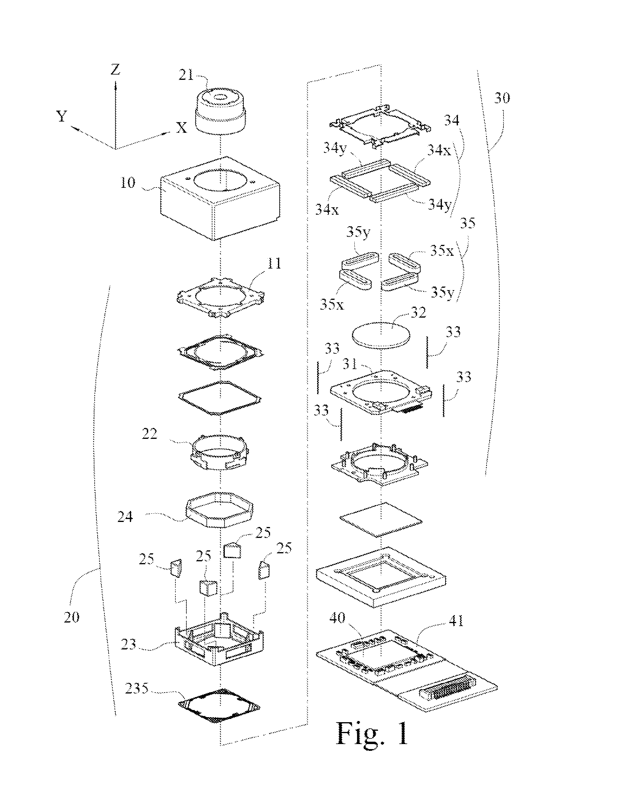
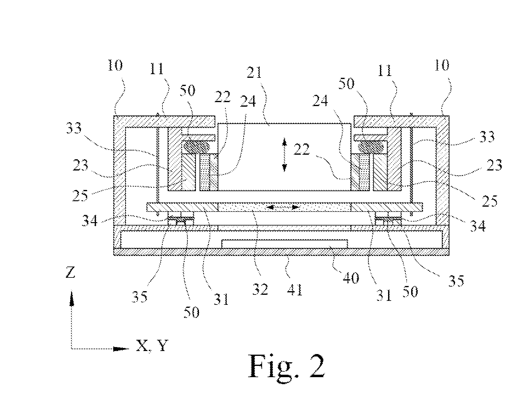
[0018]Please refer to FIG. 1 that is an exploded perspective view of an anti-shake lens focusing module with resonance suppressing structure according to the present invention. As shown, the anti-shake lens focusing module includes a housing 10, a lens focusing structure 20, an anti-shake structure 30, and an image sensor 40. The lens focusing structure 20, the anti-shake structure 30 and the image sensor 40 all are located in the housing 10 on an optical axis.
[0019]The housing 10 is provided with a top plate 11. The lens focusing structure 20 holds a lens 21 thereto and moves the lens 21 forward or backward along the optical axis, i.e. in a z-axis direction, to achieve the purpose of auto focusing, so that an image can be focused on the image sensor 40. The anti-shake structure 30 is able to move in a direction perpendicular to the optical axis or z-axis, such as to move in x-axis or y-axis direction, so as to achieve the purpose of image correction. The image sensor 40 is arranged...
second embodiment
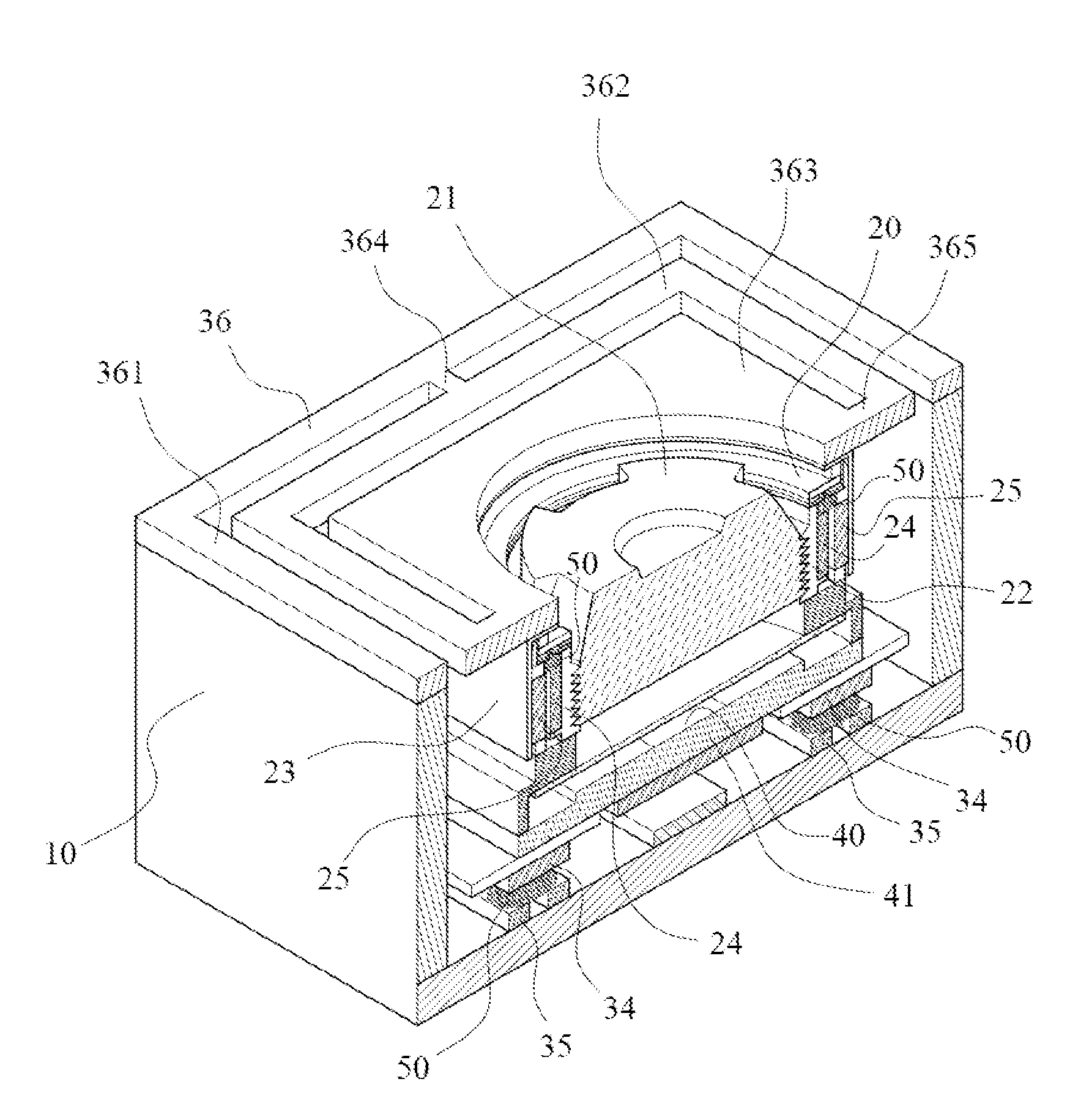
[0031]Preferably, in the second embodiment, there are four flexible elements in the form of suspension lines 33 as shown in FIG. 3. Alternatively, there can be only one flexible element in the form of a plate spring 36 as shown in FIG. 4. FIG. 4 is a cutaway view showing an embodiment of the present invention having an anti-shake structure 30 using a plate spring 36 as a flexible element thereof. With the plate spring 36, the lens focusing structure 20 is suspended in the housing 10 to locate on the optical axis, so that the first immovable part of the lens focusing structure 20 also constitutes the second movable part.
[0032]Please also refer to FIG. 5 that is a perspective view of an embodiment of the plate spring 36. As shown, the plate spring 36 includes an outer fixed portion 361, an outer movable portion 362, and an inner movable portion 363. The outer fixed portion 361 is fixedly connected to the top plate 11 of the housing 10. The outer movable portion 362 is located at an in...
third embodiment
[0038]Preferably, the anti-shake structure 30 in the third embodiment further includes a magnet assembly 34 and a winding assembly 35. The magnet assembly 34 includes at least one x-axis magnet and at least one y-axis magnet; and the winding assembly 35 includes at least one x-axis winding and at least one y-axis winding. Further, the winding assembly 35 is arranged corresponding to the magnet assembly 34 without contacting with the latter.
[0039]One of the magnet assembly 34 and the winding assembly 35 is connected to the housing 10 or other element connected thereto and thereby constitutes an element of the second immovable part. The other one of the magnet assembly 34 and the winding assembly 35 is connected to the carrier substrate 41 to constitute an element of the second movable part. Further, the shock-absorbing material 50 is provided between the magnet assembly 34 and the winding assembly 35.
[0040]FIG. 7 is an assembled sectional side view of a fourth embodiment of the prese...
PUM
 Abstract
Description
Claims
Application Information
 - R&D
- Intellectual Property
- Life Sciences
- Materials
- Tech Scout
- Unparalleled Data Quality
- Higher Quality Content
- 60% Fewer Hallucinations
Browse by: Latest US Patents, China's latest patents, Technical Efficacy Thesaurus, Application Domain, Technology Topic, Popular Technical Reports.
© 2025 PatSnap. All rights reserved.Legal|Privacy policy|Modern Slavery Act Transparency Statement|Sitemap|About US| Contact US: help@patsnap.com