
Virtual badge, device and method

a virtual badge and badge technology, applied in the field of electronic identification, can solve the problems of not being equipped with a path to follow or an area, not being able to associate a written description or code with a specific waypoint in the unit, and being far too complicated for the common user without prior instructions, so as to minimize the threat of counterfeiting virtual badges and facilitate users

Active Publication Date: 2013-02-28
DISASTER SOLUTIONS LLC
View PDF2 Cites 55 Cited by
  • Summary
  • Abstract
  • Description
  • Claims
  • Application Information

AI Technical Summary

Benefits of technology

The virtual badge system is a new technology that enhances the subject matter of the patent by using advanced mobile art. It allows users to display customizable data, photos, and videos on their cell phones or other electronic devices and replicate what a typical plastic badge can display. The virtual badge can be tracked and scanned for various applications. This system can be used in conjunction with existing software systems and is designed to offer more efficient management and security options. The patent aims to introduce a new technology that allows users to scan virtual badges with their own devices and remove the need for expensive smart phones.

Problems solved by technology

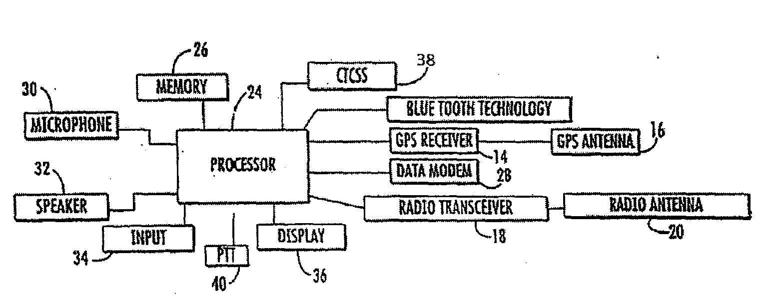
While this unit can download a given day's track to a base unit, it does not have BLUETOOTH® technology and therefore must be hard wired to the base unit to store its track.
Further, the use of the unit is far too complicated for the common user without prior instructions.
In addition, the user cannot associate a written description or code with a specific waypoint in the unit.
While these units can download a path traversed by a user, they are not equipped to be uploaded with a path to follow or an area to search.
Further, they cannot associate a specific written condition or code with a waypoint.
While these units can download a path traversed by a user, they are not equipped to be uploaded with a specific path to follow or an area to search.
In addition they cannot associate a written description or code with a specific way point.

Method used


Image

  • Virtual badge, device and method
  • Virtual badge, device and method
  • Virtual badge, device and method

Examples


Embodiment Construction

[0092]While the present invention is a susceptible embodiment in various forms, there is shown in the drawings and will hereinafter be described a presently preferred, albeit not limiting, embodiment with the understanding that the present disclosure is to be considered an exemplification of the present invention and is not intended to limit the invention to the specific embodiments illustrated.

[0093]The present invention creates a system comprising of “backend” software (software adapted to provide necessary functionality for server) on a web based or laptop server synchronized with a “front-end” software, such as software adapted to be used by a display device, including an electronic display device capable of displaying images or text, such as a cell phone or tablet computer, to make the device function accordingly, i.e. properly display the information as a virtual badge, displayed on the electronic display device. The backend software system is designed for, but is not limited ...


PUM


Abstract

A system, method, and device comprising a virtual badge are disclosed. A virtual badge can be displayed on a cell phone or in another linked portable device, and for security purposes, has images which can be scanned, and the capability to alternate colors and / or self-destruct on a pre-set schedule. Whether for after a disaster or for daily use, the system uses cell phones or mobile devices loaded with specialized software. Using plugin technologies, the system optionally can enable field collected photos and notes on customizable forms to be mapped, tracked, and time / date stamped—including in a 100% disconnected environment. A modifiable virtual badge can aid in inventory, accountability, organization, and efficiency. The system can be employed by the “Whole Community”—citizens, businesses, not-for-profits, and government agencies—for social media, business, cleanup, insurance adjusters, or personnel focused on day to day operations or on mitigation, preparedness, response, and recovery.

Description

REFERENCE TO RELATED APPLICATIONS[0001]In accordance with 37 C.F.R 1.76, a claim of priority is included in an Application Data Sheet filed concurrently herewith. Accordingly, the present invention claims the benefit of the filing date and / or priority under 35 U.S.C. §119(e), 120, 121, and / or 365(c) to U.S. Provisional Patent Application No. 61 / 709,844, filed on Oct. 4, 2012; entitled, “VIRTUAL BADGE, DEVICE AND METHOD”, and is a continuation-in-part of U.S. patent application Ser. No. 13 / 536,618, filed Jun. 28, 2012, entitled, “GPS PATHFINDER CELL PHONE AND METHOD”, which is a continuation-in-part of U.S. patent application Ser. No. 13 / 524,724, filed Jun. 15, 2012, entitled, “GPS PATHFINDER CELL PHONE AND METHOD”, which is a continuation-in-part of application U.S. patent application Ser. No. 13 / 296,874, filed Nov. 15, 2011, entitled, “GPS PATHFINDER CELL PHONE AND METHOD”, which is a continuation-in-part of application U.S. patent application Ser. No. 12 / 410,003, filed Mar. 24, 20...

Claims


Application Information

Patent Timeline
IPC IPC(8): G06F17/30G06F17/00G06K5/00
CPCG06Q10/00G07C9/00111G07C9/00103G07C9/00079G07C9/253G07C9/27G07C9/28
Inventor LEWIS, SCOTT
Owner DISASTER SOLUTIONS LLC
Learn More