
Mesa-type quartz-crystal vibrating piece and quartz crystal device

Inactive Publication Date: 2013-02-21
NIHON DEMPA KOGYO CO LTD
View PDF7 Cites 4 Cited by
  • Summary
  • Abstract
  • Description
  • Claims
  • Application Information

AI Technical Summary

Benefits of technology

The present invention provides a way to reduce the CI value (which describes the effectiveness of a quartz-crystal vibrating piece) in a smaller version of this device. This can be done while still ensuring that the device can still oscillate at high levels. The invention also finds a way to prevent the vibration of the quartz-crystal vibrating piece from being negatively impacted.

Problems solved by technology

In view of this, a conductive adhesive and a supporting portion may adversely affect a vibration of the quartz-crystal vibrating piece.

Method used


Image

  • Mesa-type quartz-crystal vibrating piece and quartz crystal device
  • Mesa-type quartz-crystal vibrating piece and quartz crystal device
  • Mesa-type quartz-crystal vibrating piece and quartz crystal device

Examples


first embodiment

Overall Configuration of a First Crystal Unit 100

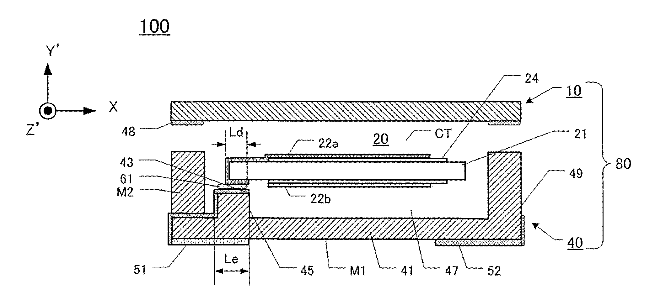
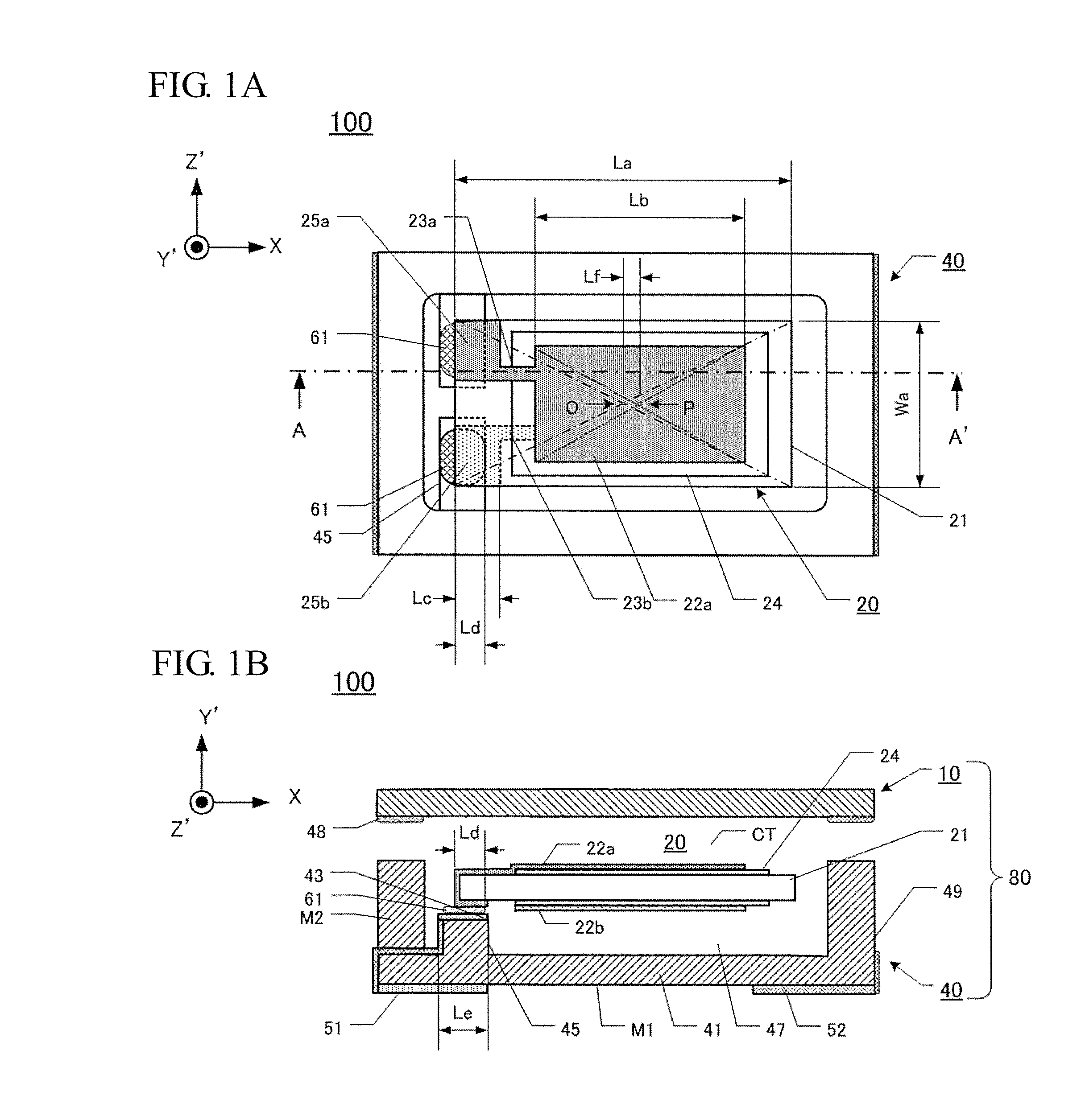
[0016]The overall configuration of the first crystal unit 100 will be described by referring to FIGS. 1A and 1B. FIG. 1A is a plan view of the first crystal unit 100 without a first lid 10 according to the first embodiment. FIG. 1B is a cross-sectional view taken along the line A-A′ of the first crystal unit 100 before the first lid 10 and a ceramic base plate 40 are bonded together.

[0017]Here, the quartz-crystal vibrating piece employs an AT-cut quartz-crystal vibrating piece 20. That is, the AT-cut quartz-crystal vibrating piece has a principal surface (in the Y-Z plane) that is tilted by 35° 15′ about the Y-axis of the crystal coordinate system (XYZ) in the direction from the Z-axis to the Y-axis around the X-axis. Accordingly in the first embodiment, the new axises tilted with reference to the axis directions of the AT-cut quartz-crystal vibrating piece are denoted as the Y′ axis and the Z′ axis. Therefore, in the first embodiment...

second embodiment

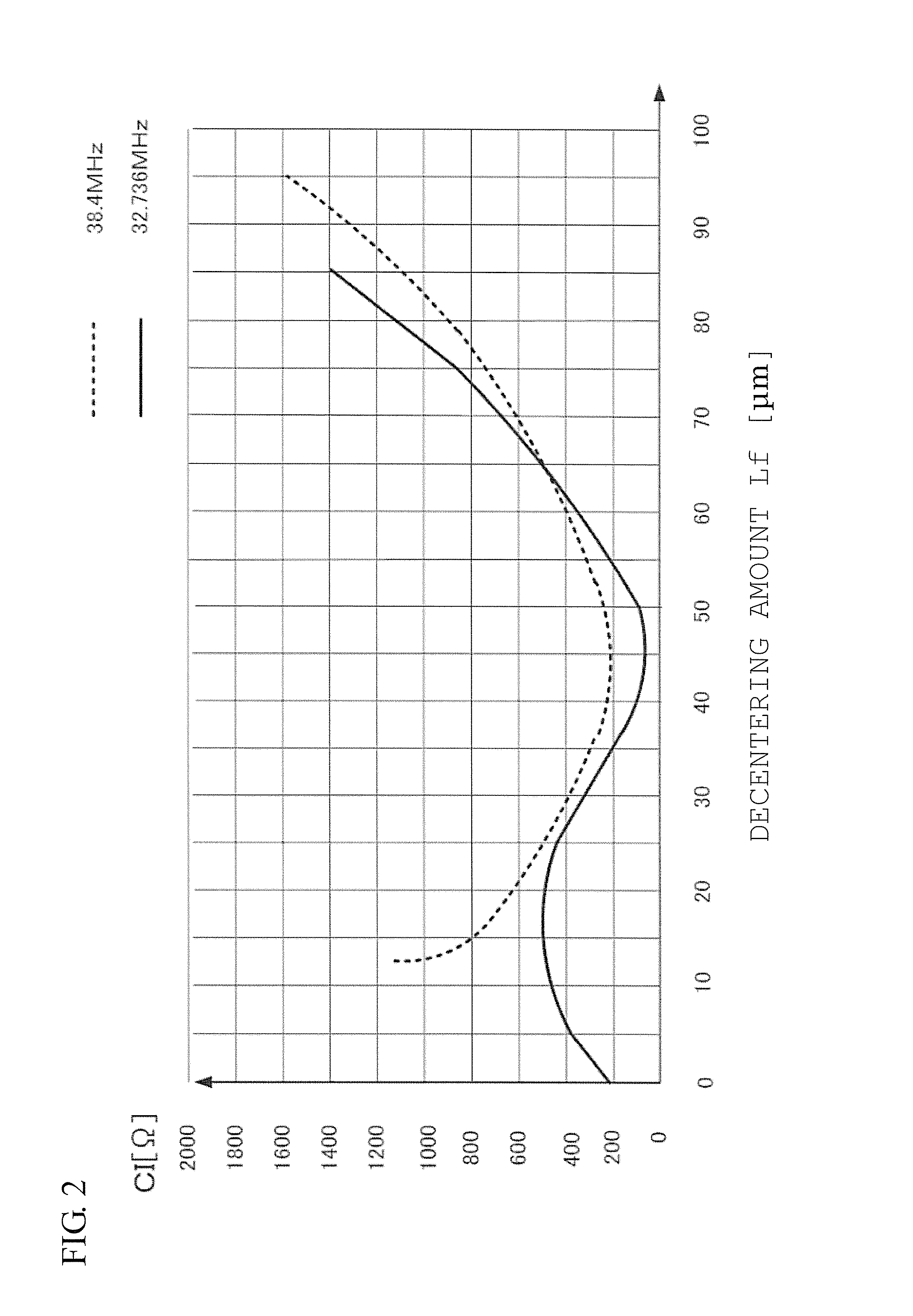
[0029]In order to further decrease the CI value, the decentering amount Lf may be set within the following range. In the case where the decentering amount Lf is 35 μm to 55 μm, the CI value indicates more preferred value equal to or less than 300 Ω. Further, in the case where the decentering amount Lf is 40 μm to 50 μm, the CI value indicates approximately the minimum value, and then this is more preferred. Overall configuration of a second crystal unit 110

[0030]The overall configuration of the second crystal unit 110 will be described by referring to FIGS. 3, 4A, and 4B. FIG. 3 is an exploded perspective view of the second crystal unit 110 from a second lid 12. FIG. 4A is a cross-sectional view taken along the line B-B′ of FIG. 3 after a quartz-crystal frame 30, a second base plate 11, and the second lid 12 are bonded together. FIG. 4B is a plan view illustrating the quartz-crystal frame 30 with an excitation electrode 304a.

[0031]The second crystal unit 110 differs from the first ...


PUM


Abstract

A mesa-type quartz-crystal vibrating piece includes a vibrator in a quadrangular shape with both main surfaces, a pair of excitation electrodes on both the main surfaces, a thin portion outside of the quadrangular shape, and a pair of extraction electrodes. The thin portion has a thickness thinner than a thickness of the vibrator. The pair of extraction electrodes are extracted from the excitation electrodes to a predetermined direction. A center of a first length in the predetermined direction of the excitation electrode is decentered from a center of a second length in the predetermined direction. The second length includes a length of the vibrator and a length of the thin portion. The center of the first length is decentered toward an opposite side of the extraction electrode by 25 μm to 65 μm.

Description

CROSS-REFERENCE TO RELATED APPLICATIONS[0001]This application claims the priority benefit of Japan application serial no. 2011-178554, filed on Aug. 17, 2011. The entirety of the above-mentioned patent application is hereby incorporated by reference herein and made a part of this specification.TECHNICAL FIELD[0002]This disclosure related to mesa-type crystal units with structures that include thick portions, which are thicker than their peripheral portions and used as vibrators, in the centers of quartz-crystal vibrating pieces.DESCRIPTION OF THE RELATED ART[0003]Nowadays, there is a need for a further downsized quartz crystal device such as a crystal unit as electronic devices are downsized. The downsized electronic devices make distances between excitation electrodes and a region that supports and secures a quartz-crystal vibrating piece narrow. In view of this, a conductive adhesive and a supporting portion may adversely affect a vibration of the quartz-crystal vibrating piece.[0...

Claims


Application Information

Patent Timeline
IPC IPC(8): H01L41/047H01L41/053
CPCH03H9/1035H03H9/0595H03H9/09H03H9/19
Inventor SASAKI, HIROYUKISHIMAO, KENJIISHIKAWA, MANABU
Owner NIHON DEMPA KOGYO CO LTD
Learn More