
Wiper linkage

a technology of wiper linkage and rotary disc, which is applied in the direction of vehicle maintenance, gearing, vehicle cleaning, etc., can solve the problems of large radius of motor crank trajectory, passenger side, unfavorable transmission ratio between the two driving oscillating lengths, etc., to improve the functional quality of the wiper linkage, improve the kinematics, and expand the use options.

Inactive Publication Date: 2013-02-21
ROBERT BOSCH GMBH
View PDF24 Cites 3 Cited by
  • Summary
  • Abstract
  • Description
  • Claims
  • Application Information

AI Technical Summary

Benefits of technology

The invention is a wiper linkage for a windshield wiper system in a motor vehicle that improves its performance and expands its use options. The linkage has better kinematics, meaning it can move more smoothly and with greater precision. It has two different crank radii, which results in optimized movement of the wiper arms and reduces the difference in oscillating length between the arms. This also reduces the likelihood of rattling and improves system performance in critical environmental conditions. The linkage is designed with an angled axis of symmetry, which makes it easy to achieve different crank radii for the two arms. This design is cost-effective and allows for smaller components. Overall, the invention enhances the functionality and reliability of the wiper linkage.

Problems solved by technology

This results in a large radius of the motor crank trajectory which, together with the customarily small ratio of crank radius to rod length of approx.
This is disadvantageous in particular for the passenger's side, since only a short oscillating length is produced for said relatively long windshield wiper arm.
This in turn results in an unfavorable transmission ratio between the two driving oscillating lengths.
The disadvantages include relatively large wiping angle tolerances and increased internal forces in the wiper drive due to the short oscillating length.
Said high internal forces and the unfavorable ratio between windshield wiper arm length and oscillating length make the wiping system sensitive to external disturbances, which may result in rattling of the windshield wiper arms, and therefore the advantages which the reversing system with rotational speed control has do not come to bear.

Method used


Image

  • Wiper linkage
  • Wiper linkage
  • Wiper linkage

Examples


Embodiment Construction

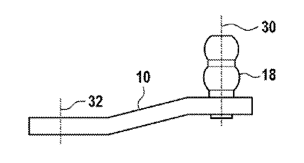
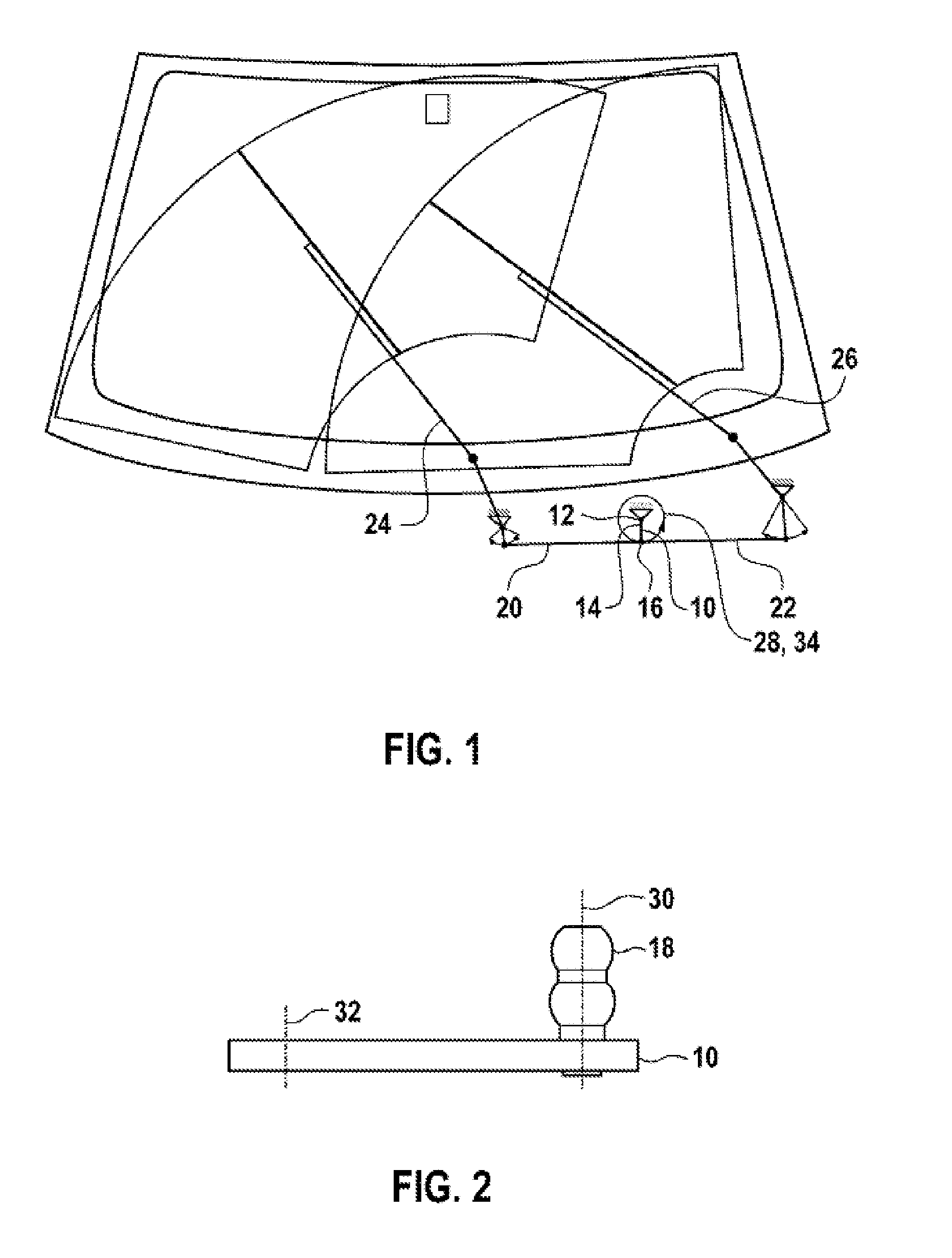
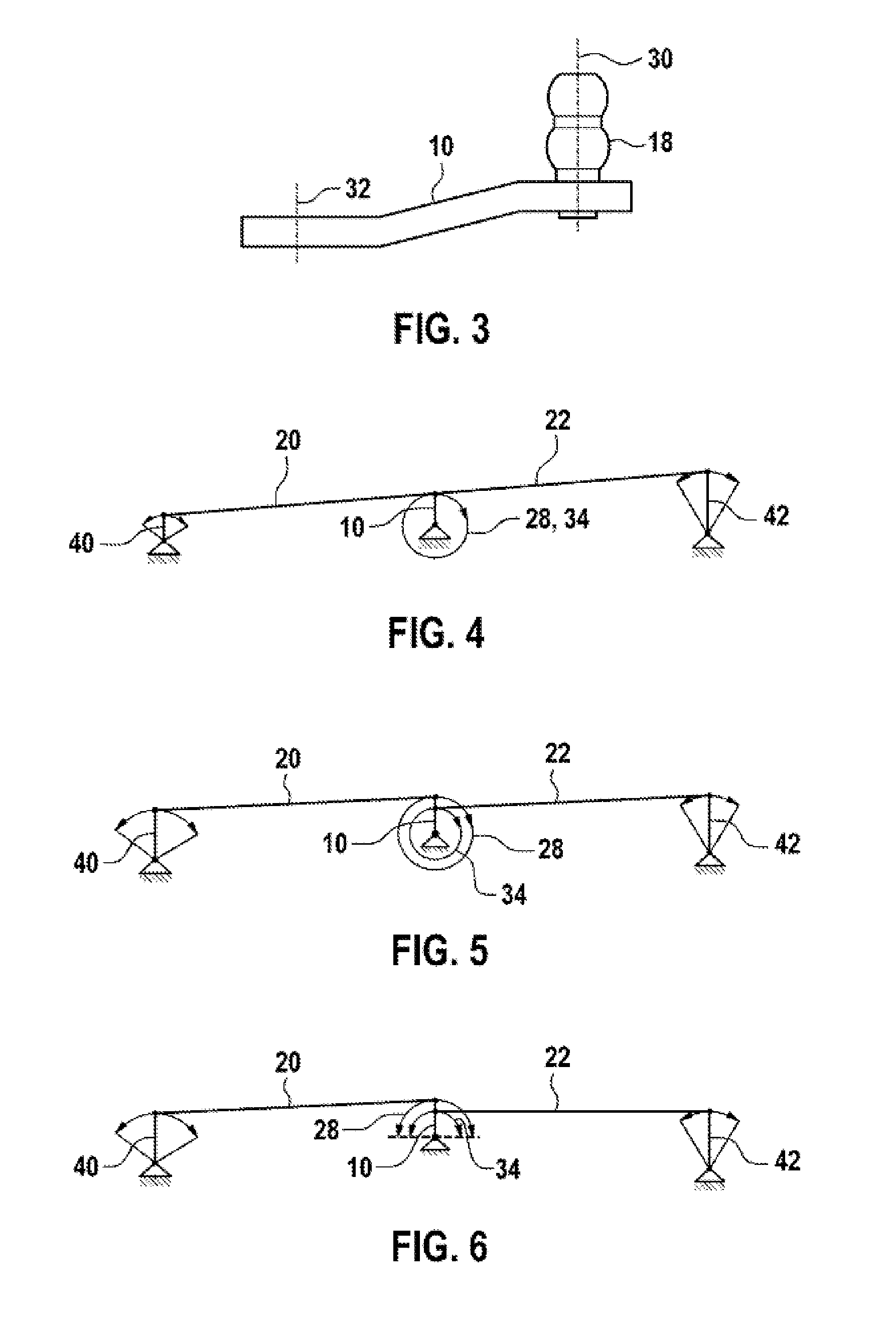
[0023]FIG. 1 shows a schematic illustration of an arrangement of a synchronizing wiper system with a known wiper linkage of a windshield wiper system for a motor vehicle, said wiper linkage having a motor crank 10 which is connected via a connecting element 12 in the form of an output shaft to a driving motor. In this case, the motor crank 10 is connected at a first end section 14 to the connecting element 12. At the second end section 16 opposite the first end section 14, the motor crank has a double ball pin 18, as illustrated in FIG. 2 and FIG. 3, on which a first articulated rod 20 and a second articulated rod 22 (not illustrated in FIG. 2 and FIG. 3) are provided. A windshield wiper arm 24 which is provided for the passenger's side of the motor vehicle is arranged on the first articulated rod 20, and the second articulated rod 22 is connected to a windshield wiper arm 26 which is arranged on the driver's side of the motor vehicle. This known synchronizing wiper system has a cra...


PUM


Abstract

A wiper linkage of a windscreen washing system for a motor vehicle, comprising a motor crank (10) with a first end section (14) and a second end section (16), wherein the motor crank (10) is connected at its first end section (14) to a drive motor via a connecting element (12), and wherein the motor crank (10) has, at its second end section (16), a double ball pin (18) which is connected to a first joint rod (20) and to a second joint rod (22), wherein by means of a rotational movement of the motor crank (10) a first crank radius (28) can be transmitted to the first joint rod (20) and a second crank radius (34) can be transmitted to the second joint rod (22), wherein according to the invention the first crank radius (28) of the first joint rod (20) has a different size from the second crank radius (34) of the second joint rod (22).

Description

BACKGROUND OF THE INVENTION[0001]The invention relates to a wiper linkage of a windshield wiper system for a motor vehicle.[0002]Wiper linkages customarily have a motor crank which is connected to an output shaft of a driving motor, in particular of a wiper motor, via which output shaft the motor crank is driven by the driving motor. A ball pin or a double ball pin is customarily provided on the motor crank and, in the case of a double ball pin, a first articulated rod for a first windshield wiper and a second articulated rod for a second windshield wiper are arranged thereon. This results in synchronized windshield wiper arms, one acting on the driver's side and one on the passenger's side. In order to obtain forces which are as low as possible at the articulated rods, the motor crank customarily has a relatively great length. This results in a large radius of the motor crank trajectory which, together with the customarily small ratio of crank radius to rod length of approx. 1 / 4 to...

Claims


Application Information

Patent Timeline
Patent Type & Authority Applications(United States)
IPC IPC(8): B60S1/34F16H21/40
CPCB60S1/163Y10T74/18232B60S1/24
Inventor ZIMMER, JOACHIM
Owner ROBERT BOSCH GMBH
Learn More