
Method for analyzing and diagnosing large scale process automation control systems

a technology for process automation and control systems, applied in the field of industrial controllers, can solve problems such as difficult, to say the least, to determine which control loops, and poor control of process variables

Active Publication Date: 2013-01-31
ABB INC
View PDF12 Cites 22 Cited by
  • Summary
  • Abstract
  • Description
  • Claims
  • Application Information

AI Technical Summary

Benefits of technology

The invention provides a method for analyzing control loops of a control system that control a process. The method includes receiving a selection of one of the control loops for analysis, generating an assessment for each of multiple key performance indicators (KPIs) for the selected control loop, and displaying the types of control data and the assessments of the KPIs on a single screen of a graphical user interface. The technical effects of this invention include enabling quick analysis and assessment of multiple control loops simultaneously, providing users with useful information about the performance of the control system, and improving the overall efficiency of the control system.

Problems solved by technology

A control loop, such as the one described above can experience a problem that results in poor control of the process variable.
The problem can be with the final control element, the sensor, tuning parameters of the controller, or something else.
In such an industrial facility, it is difficult, to say the least, to determine which control loops are experiencing problems, especially when a problem in one control loop may adversely affect other control loops.

Method used


Image

  • Method for analyzing and diagnosing large scale process automation control systems
  • Method for analyzing and diagnosing large scale process automation control systems
  • Method for analyzing and diagnosing large scale process automation control systems

Examples


Embodiment Construction

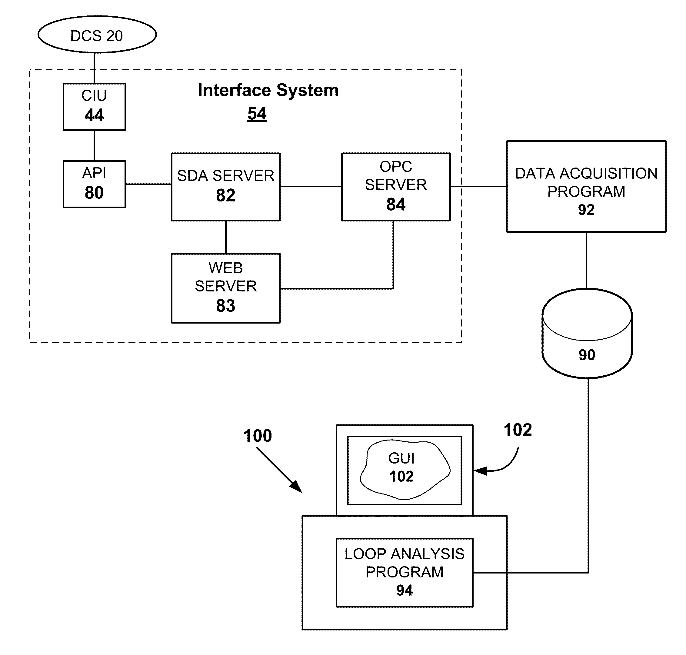
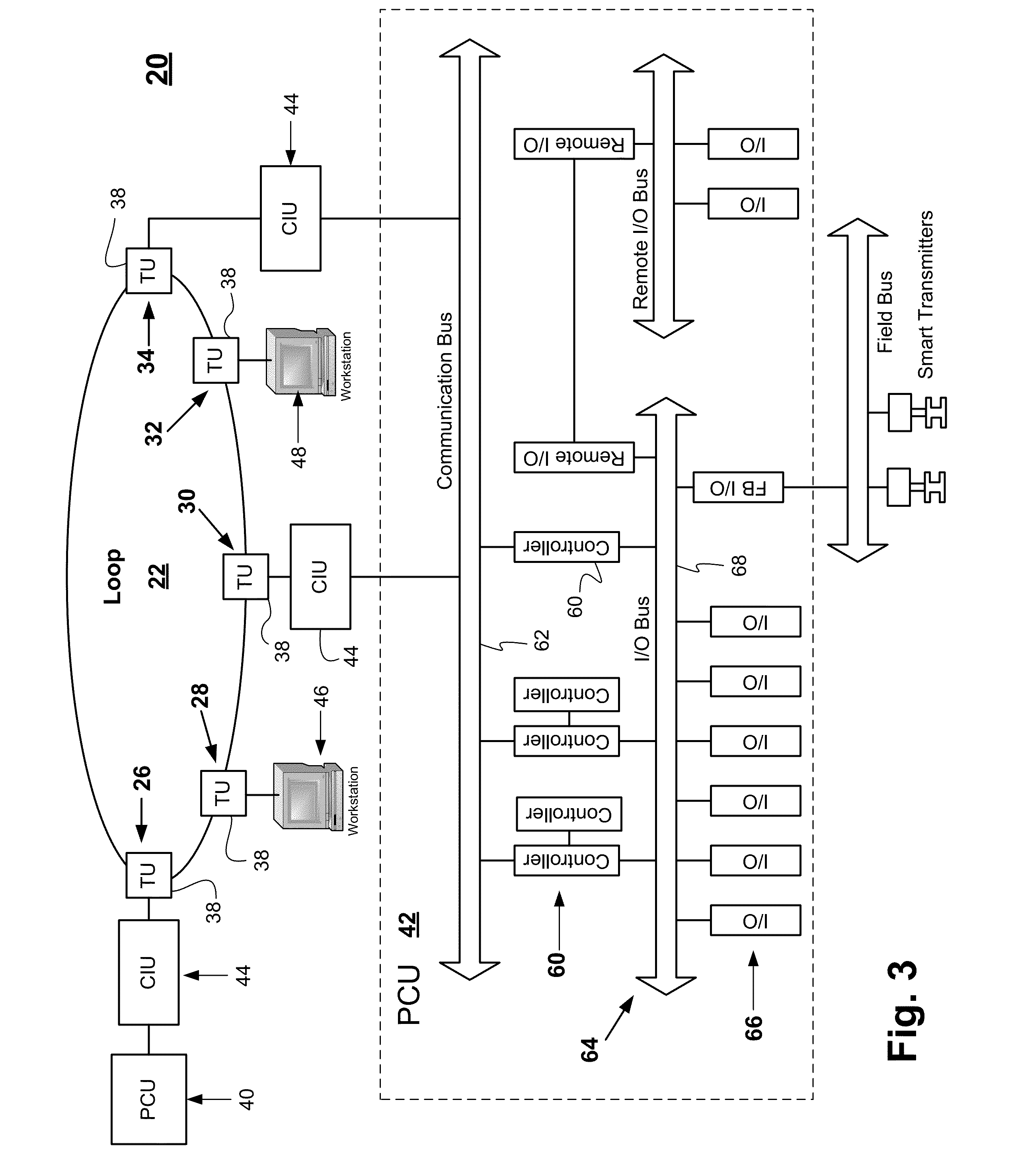
[0039]It should be noted that in the detailed description that follows, identical components have the same reference numerals, regardless of whether they are shown in different embodiments of the present invention. It should also be noted that in order to clearly and concisely disclose the present invention, the drawings may not necessarily be to scale and certain features of the invention may be shown in somewhat schematic form.

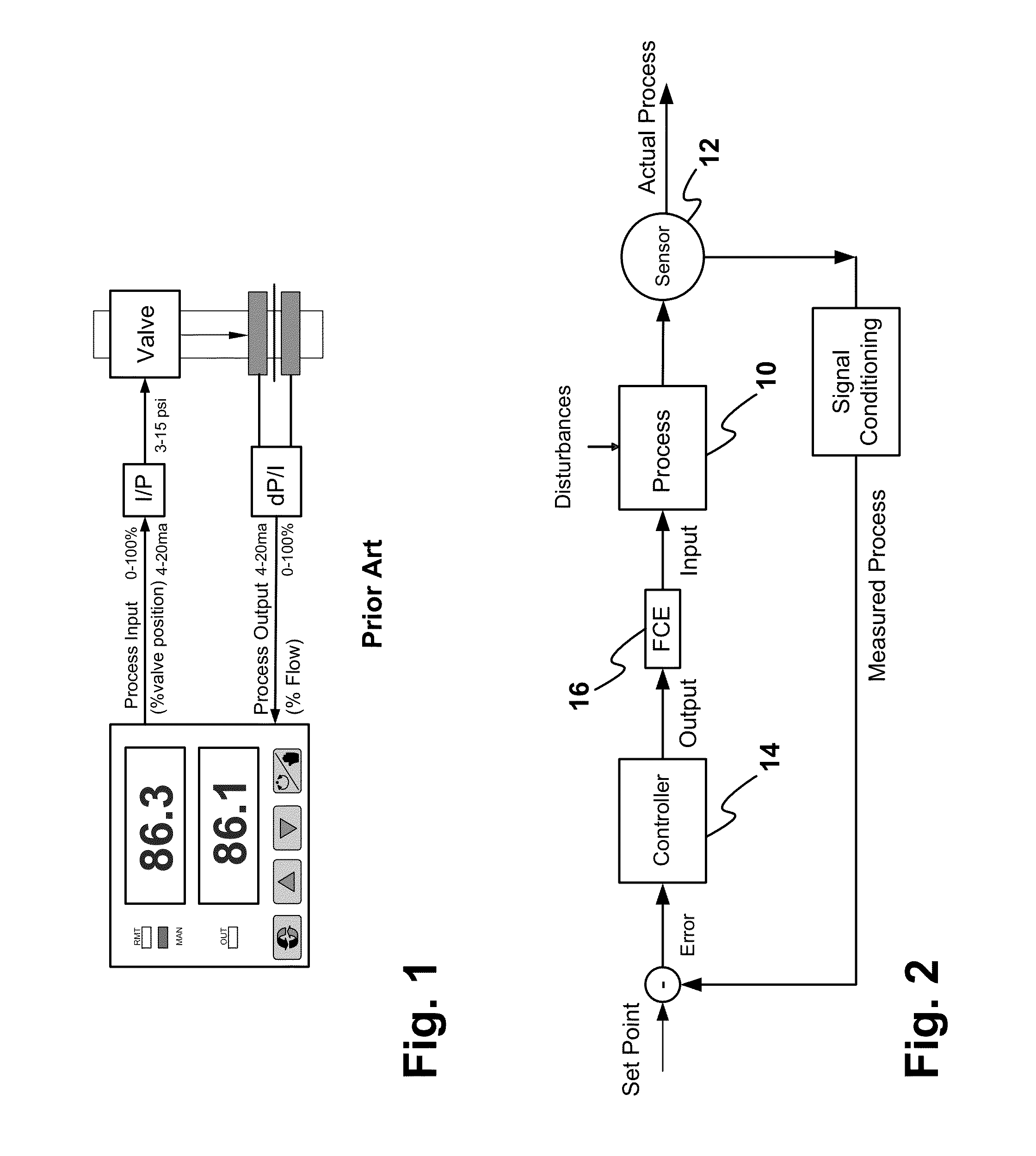
[0040]While the area of process control is quite vast, with many different control loops being utilized, nearly all industrial single loop control applications can be represented with a block diagram, such as is shown in FIG. 2. In this diagram, the process 10 is any industrial process having a variable that can be measured by a sensor 12, which is in direct or indirect contact with the process 10. The sensor 12 is a transducer that converts a physical property (variable) of the process 10 into a signal that can be transmitted. This signal (which represents ...


PUM


Abstract

A method is provided for analyzing and diagnosing a large scale process automation control system having a plurality of control loops. Assessments for pre-defined key performance indicators (KPIs) are automatically generated for control, process and signal sections of each control loop. The automatically generated assessments of the pre-defined KPIs may be displayed in a graphical user interface (GUI) of a computer. A user may change the automatically generated assessments of the pre-defined KPIs. Different data views may also be displayed in the GUI. The data views include time series trends for measured process variable, controller output, controller set point and error, as well as controller parameter clustering views in two-dimensional and three-dimensional plots.

Description

CROSS-REFERENCE TO RELATED APPLICATION[0001]This application claims the benefit of U.S. provisional patent application No. 61 / 435,482 filed on Jan. 24, 2011, which is hereby incorporated by reference in its entirety.BACKGROUND OF THE INVENTION[0002]This invention relates to industrial controllers and more particularly to evaluating the performance of industrial controllers.[0003]Industrial process controllers (hereinafter, simply “controllers”) have many different configurations and are used in many different applications. Controllers may be mounted in a control room or may be part of a distributed control system. Controllers are designed to maintain a process variable at a desired reference point known as a set point. Process variables can be flow, pressure, temperature, consistency, speed, current, level, pH, etc. A conventional example of how a controller may be physically connected in an industrial process is shown in the functional block diagram of FIG. 1. In this example, a co...

Claims


Application Information

Patent Timeline
Patent Type & Authority Applications(United States)
IPC IPC(8): G05B15/02G06F3/01
CPCG05B23/0216G05B23/0272G05B23/02
Inventor STARR, KEVIN DALEMAST, TIMOTHY ANDREWGARVERICK, ROBERT TRENT
Owner ABB INC
Learn More