
Fastening mechanism for electronic device and an electronic device using the same

Inactive Publication Date: 2013-01-31
WISTRON CORP
View PDF3 Cites 8 Cited by
  • Summary
  • Abstract
  • Description
  • Claims
  • Application Information

AI Technical Summary

Benefits of technology

The present invention provides an electronic device that allows for easy installation and removal of electronic elements without screw fasteners. The device has a fastening mechanism that provides a constant frictional force between the device's components, ensuring smooth installation and removal. Overall, the invention improves the convenience and speed of electronic device assembly and disassembly.

Problems solved by technology

Taking a peripheral electronic element for assembly to a computer through screw fasteners as an example, the disadvantage lies in that a tool needs to be used to remove the screw fasteners one by one, and after the peripheral electronic element is replaced, the screw fasteners need to be re-fastened in sequence.
For such a design, the removal and installation process is both complicated and time consuming.
In addition, the removed screw fasteners generally are held in hand or placed at random, and are easily lost.

Method used


Image

  • Fastening mechanism for electronic device and an electronic device using the same
  • Fastening mechanism for electronic device and an electronic device using the same
  • Fastening mechanism for electronic device and an electronic device using the same

Examples


Embodiment Construction

[0025]The above-mentioned and other technical contents, features, and effects of this invention will be clearly presented from the following detailed description of one embodiment in coordination with the reference drawings.

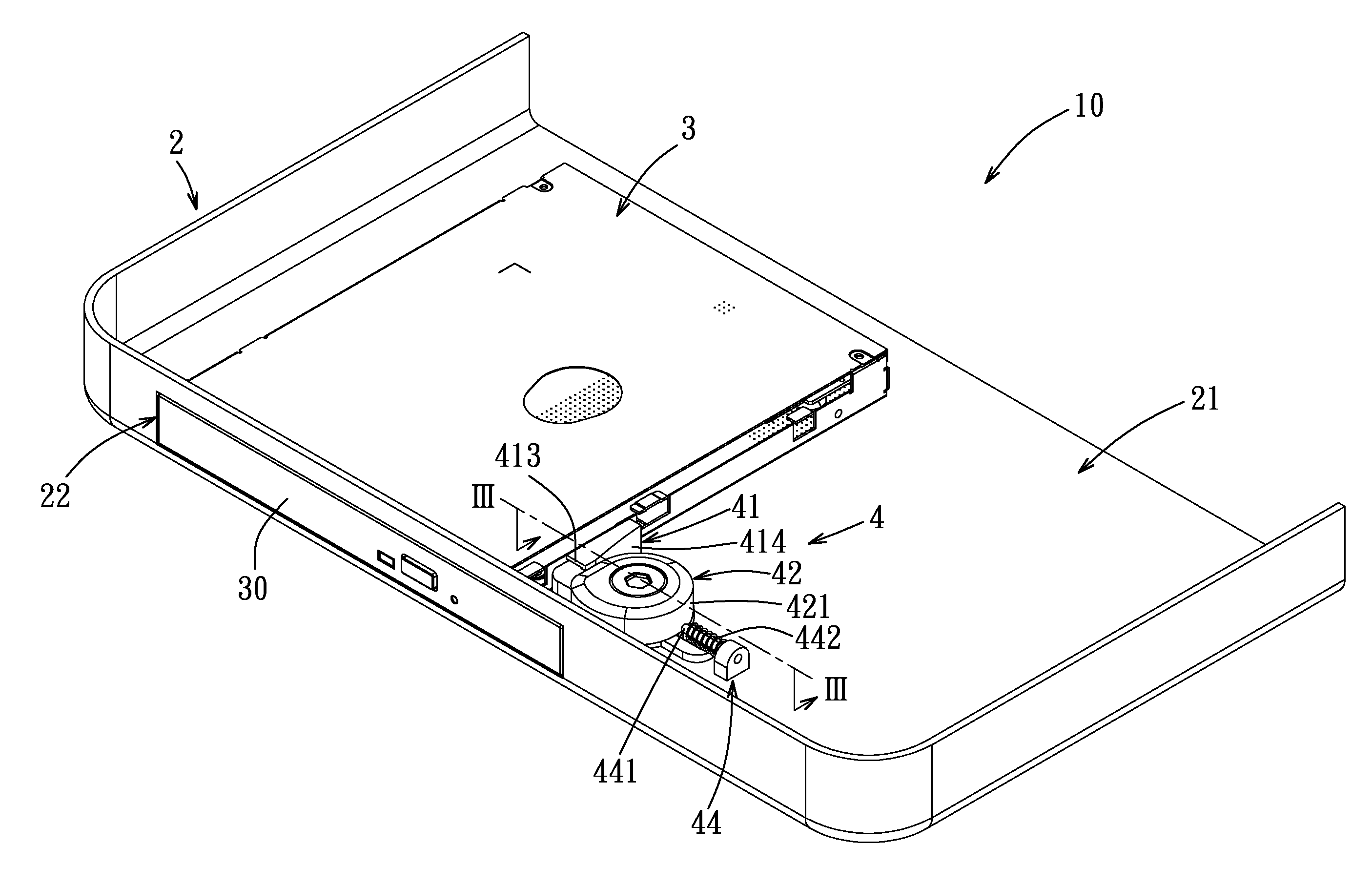
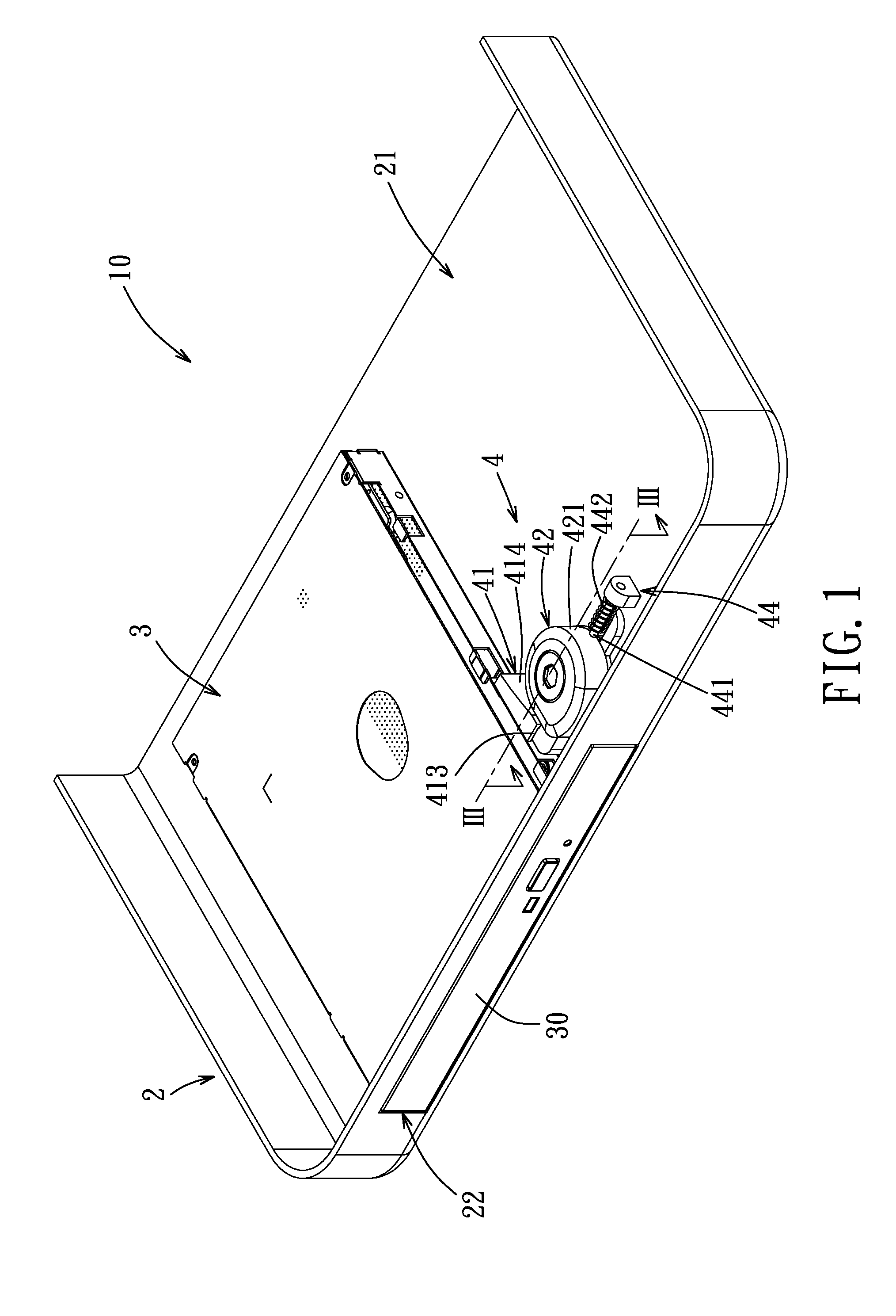
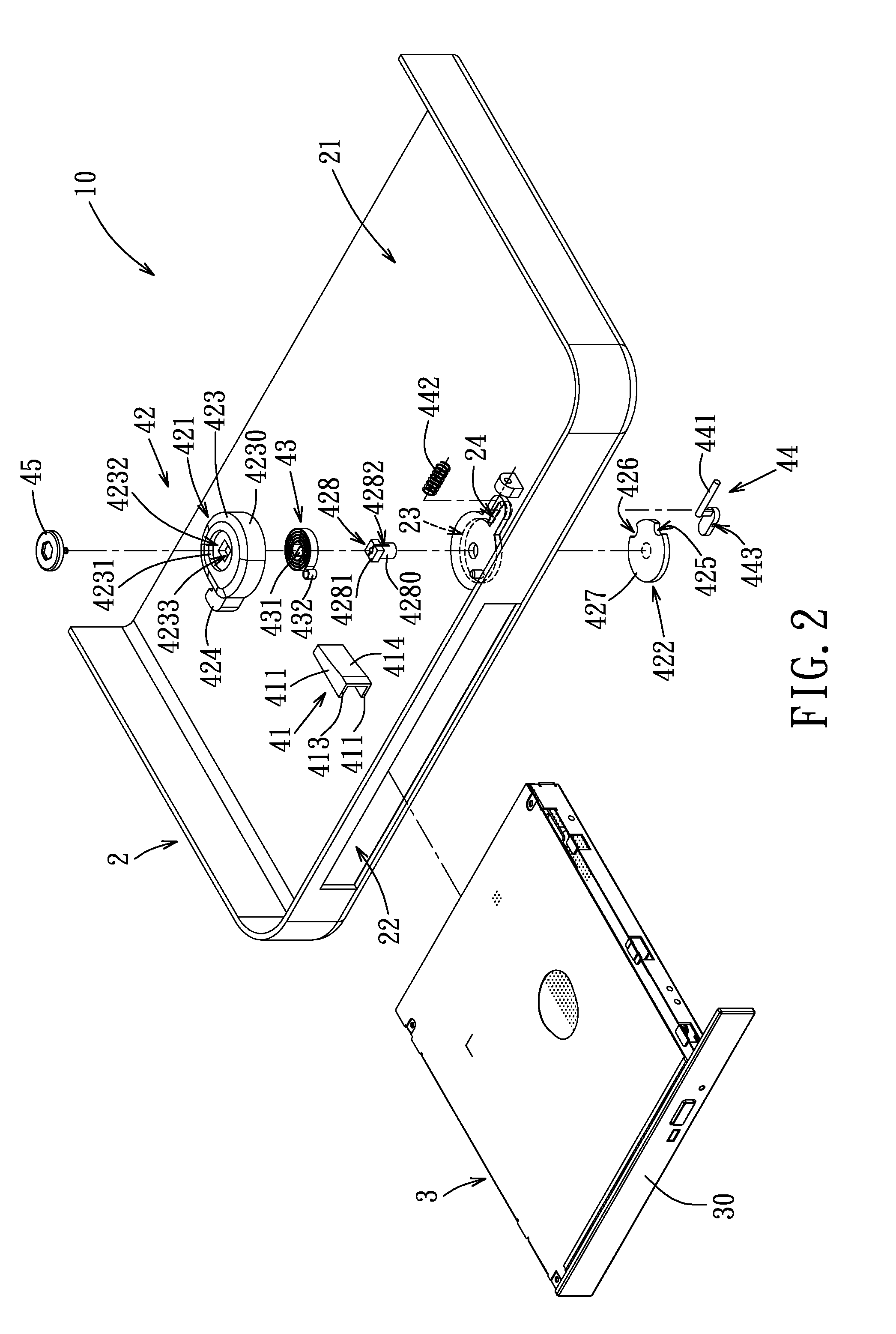
[0026]Referring to FIGS. 1 and 2, an embodiment of an electronic device 10 of the present invention comprises a housing 2, an object 3 and a fastening mechanism 4. The housing 2 is formed with an opening 22 and a through hole 23. In this embodiment, the object 3 is an optical disk drive, which is disposed within the housing 2 with a front panel 30 thereof covering the opening 22, and which is operable to be removed from the housing 2 through the opening 22.

[0027]The fastening mechanism 4 includes a nosepiece 41, a rotating unit 42, a torsion spring 43, and a locking unit 44. The nosepiece 41 is disposed at one side of the object 3, may have an elongated configuration as formed by bending a plate body, and includes two trapezoidal plate portions 411 spaced apart f...


PUM


Abstract

A fastening mechanism includes a nosepiece, a rotating unit, a torsion spring and a locking unit. The nosepiece is disposed at one side of an object removably disposed in a housing. The rotating unit includes a wheel body including a peripheral wall with an outer peripheral friction surface disposed in frictional contact with a side surface of the nosepiece and a rotating disc formed with a notch. The rotating unit is operable to rotate in a releasing direction relative to the housing as biased by the torsion spring to move the object away from the housing through an opening by virtue of the frictional contact. The locking unit releasably engages the rotating disc to dispose the rotating unit at a stopped position.

Description

CROSS-REFERENCE TO RELATED APPLICATION[0001]This application claims priority of Taiwanese Patent Application No. 100127019, filed on Jul. 29, 2011, the disclosure of which is incorporated herein by reference.BACKGROUND OF THE INVENTION[0002]1. Field of the Invention[0003]The invention relates to a fastening mechanism for an electronic device, and more particularly to a fastening mechanism for use in an electronic device to fasten electronic elements.[0004]2. Description of the Related Art[0005]With the progress of computer technologies, the update of peripherals is becoming increasingly faster, and users often need to remove or install peripheral electronic elements (e.g., an optical disk drive) in order to upgrade or expand peripheral electronic elements of a computer. Therefore, a computer allowing easy removal and installation of peripheral electronic elements can better satisfy the users' needs.[0006]Taking a peripheral electronic element for assembly to a computer through screw...

Claims


Application Information

Patent Timeline
IPC IPC(8): H05K5/02F16B21/14
CPCG06F1/1658Y10T403/583G06F1/187F16B2200/69
Inventor KO, PING-YU
Owner WISTRON CORP
Learn More