Eureka AIR delivers breakthrough ideas for toughest innovation challenges, trusted by R&D personnel around the world.

Image forming apparatus

a technology of forming apparatus and forming plate, which is applied in the direction of digitally marking record carriers, instruments, electrographic processes, etc., can solve the problems of insufficient amount of the density of the developing plate, and the insufficient charge on the toner supplied, so as to increase the combined-color reproduction accuracy

Active Publication Date: 2013-01-31
RICOH KK
View PDF1 Cites 6 Cited by
  • Summary
  • Abstract
  • Description
  • Claims
  • Application Information

AI Technical Summary

Benefits of technology

This patent describes an image forming apparatus that can create a combined-color toner image by transferring multiple primary-color toner images onto a surface. The apparatus includes an image forming unit to create the separate color toner images, a transfer unit to bring a contact member into contact with the image carrier to create a transfer nip, and a control unit to manage the image forming and transfer processes. The control unit includes an area searching unit to find a suitable color measurement area, a color measuring unit to perform color measurement on the combined-color toner image, and a deposition-amount detecting unit to measure the toner deposition amount. The control unit can adjust control parameters for the image forming unit to improve color reproduction accuracy or stabilize the toner deposition amount.

Problems solved by technology

When printings are successively performed with an electrophotographic image forming apparatus, an amount of charge on toner in a developer stored in a developing device can be changed greatly, resulting in deviation of a developing density.
The amount of charge on the toner supplied into the developing device gradually increases as the toner is mixed and stirred with carrier particles in the developer; however, immediately after the toner has been supplied, the amount of charge on the toner is not sufficient.
Meanwhile, when images having a low image-area ratio are successively printed, a condition where only a small amount of toner is supplied to the developer continues long, causing a large part of toner in the developer to be retained while being stirred in the developing device for a long period of time.
Such an increase or decrease in the developing density results in deviation of the developing density.
However, this approach is disadvantageous in that combined colors are continuously printed in color tones that slightly differ from those of desired, or target colors.
A combined color is reproduced by overlaying a plurality of primary-color toner images on one another; however, the approach discussed above causes a combined color to be unfavorably printed in a color tone slightly different from that of a desired color.
A mixture ratio of different color toners is adjusted according to area-coverage ratios of the primary-color toner images to be overlaid; however, the difference between a reproduced color tone and a desired color tone results from accumulation of various factors and it is difficult to clearly specify the cause.
However, the test product configured as discussed above has a disadvantage below.
When an image to be printed according to an instruction from a user has great variation in color tone, there can be a situation where the image has no suitable color measurement area suitable for color measurement and therefore the color-reproduction-accuracy increasing process cannot be performed.
However, if the situation where the color-reproduction-accuracy increasing process cannot be performed is kept for successive printings of dozens of sheets, color tone of the printouts can be disturbed greatly.
Such a sorting operation is considerably burdensome and therefore it is substantially impracticable to employ the configuration in which the test printout on which a combined-color toner image is produced for color measurement.

Method used


Image

  • Image forming apparatus
  • Image forming apparatus
  • Image forming apparatus

Examples


experiment 1

Comparative Example

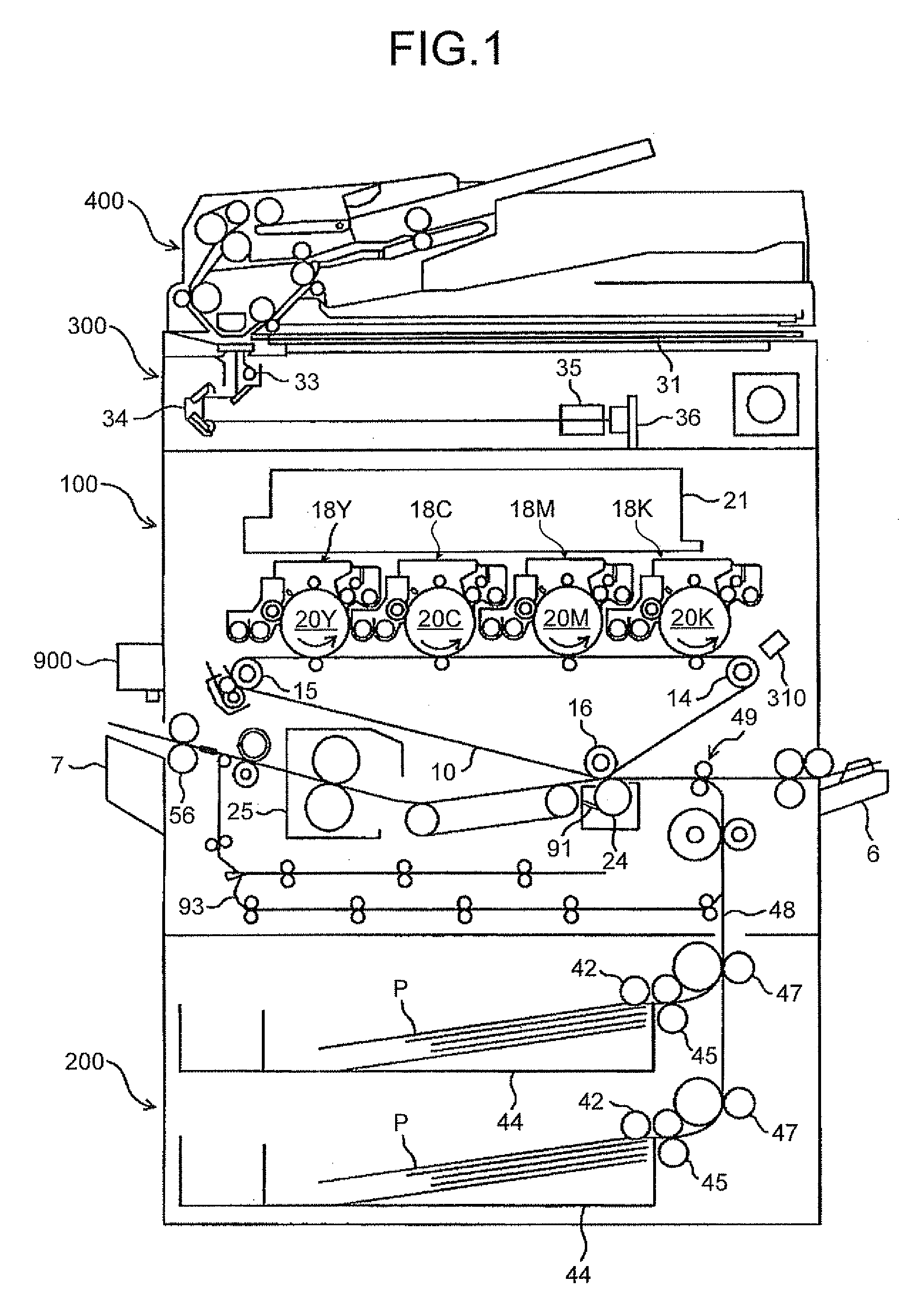
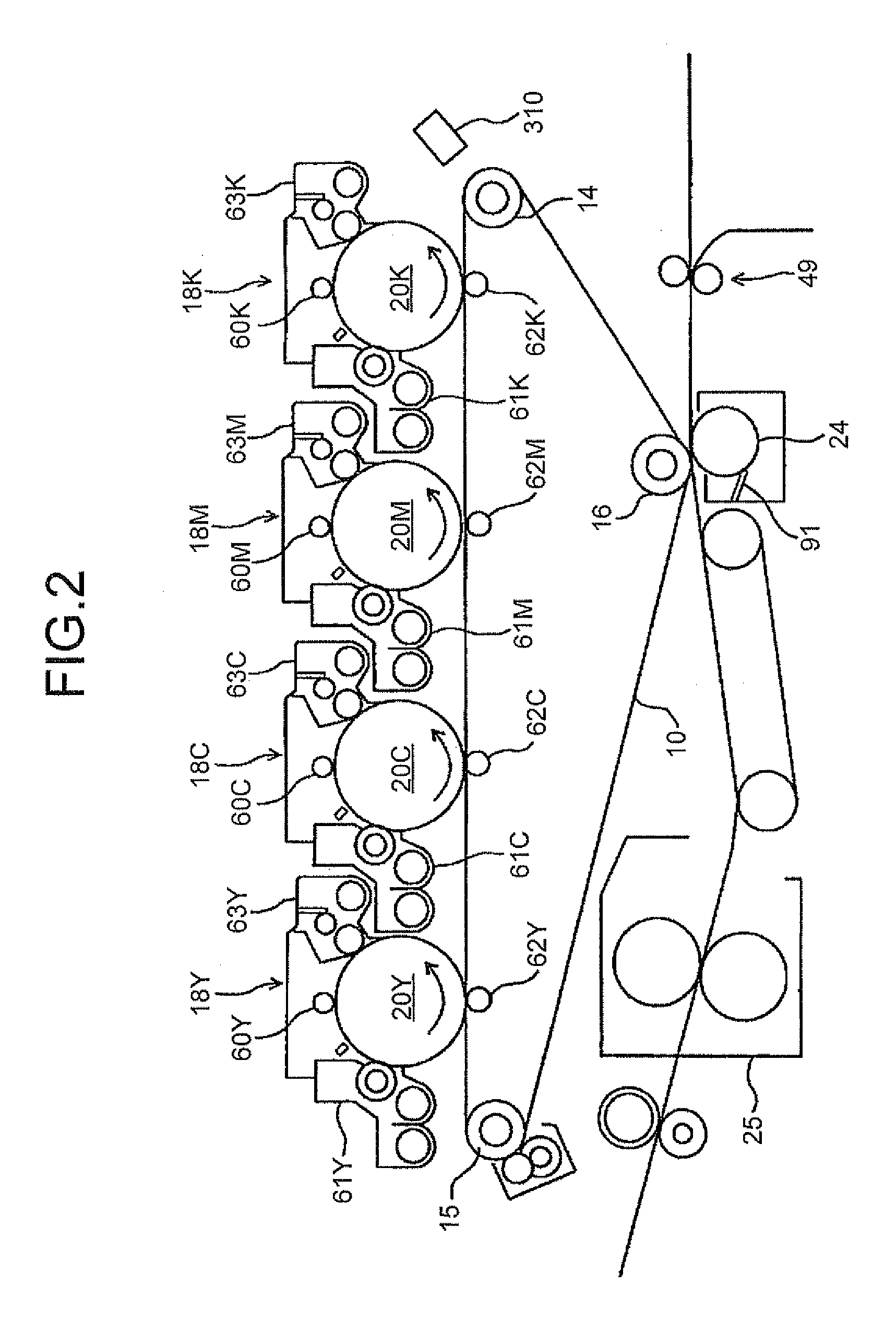
[0117]An experiment is carried out with a test copier having the same configuration as the copier according to the embodiment. Successive printings of a predetermined test image having a combined color on 500 sheets of the recording paper P are performed. In these successive printings, the color-reproduction-accuracy increasing process is not performed but only the deposition-amount stabilizing process is performed. The deposition-amount stabilizing process is performed on a per-printout-sheet basis. The Y-, C-, M-, and K-toner patch images Py, Pc, Pm, and Pk are formed on an area on the intermediate transfer belt 10 corresponding to an inter-sheet area, in which recording paper is not to be overlaid on the intermediate transfer belt 10. Color measurement on the test image on each of the printout sheets is performed with the line spectrometer 900, and a result of the color measurement is converted into L*a*b* colorimetric system.

[0118]FIG. 9 is a graph illustratin...

experiment 2

Embodiment

[0128]After performing successive printings of a predetermined first test image having a combined color on 400 sheets of the recording paper P, successive printings of a predetermined second test image having a combined color on 300 sheets of the recording paper P are performed. In each printing, if a suitable color measurement area is found in the image, the color-reproduction-accuracy increasing process is performed, while if a suitable color measurement area is not found in the image, the deposition-amount stabilizing process is performed rather than the color-reproduction-accuracy increasing process. As the first test image, an image including a suitable color measurement area is employed, whereas as the second test image, an image not including a suitable color measurement area is employed. Accordingly, the color-reproduction-accuracy increasing process is performed for each of the first to 400th sheets of printed output, whereas the deposition-amount stabilizing proc...


PUM


Abstract

An image forming apparatus includes a control unit configured to perform, if a suitable color measurement area suitable for color measurement of a combined color is found in an image, a color-reproduction-accuracy increasing process while, if not, to perform a deposition-amount stabilizing process. In the color-reproduction-accuracy increasing process, a control parameter is adjusted so as to reduce a difference between a result of the color measurement on the suitable color measurement area and a desired color. In the deposition-amount stabilizing process, a plurality of test primary-color toner images are formed by an image forming unit, and a control parameter for the image forming unit are adjusted so as to reduce a difference between each of results of toner deposition amount measurement on the test primary-color toner images and a corresponding target deposition amount.

Description

TECHNICAL FIELD[0001]The present invention relates to an image forming apparatus, such as a copier, a facsimile machine, or a printer.BACKGROUND ART[0002]When printings are successively performed with an electrophotographic image forming apparatus, an amount of charge on toner in a developer stored in a developing device can be changed greatly, resulting in deviation of a developing density. More specifically, a toner concentration in the developer stored in the developing device is kept within a predetermined range by supplying toner according to a drop in the toner concentration resulting from development. The amount of charge on the toner supplied into the developing device gradually increases as the toner is mixed and stirred with carrier particles in the developer; however, immediately after the toner has been supplied, the amount of charge on the toner is not sufficient. When such toner is supplied in a large amount, toner charge-to-mass ratio (Q / M) of the developer becomes re...

Claims


Application Information

Patent Timeline
Patent Type & Authority Applications(United States)
IPC IPC(8): H04N1/60
CPCG03G15/5058G03G2215/00059G03G15/0131G03G2215/0129G03G2215/0164G03G2215/00063G03G15/16G03G15/01
Inventor TOMITA, KENTAROH
Owner RICOH KK
Why Eureka
Eureka Blog
Learn More