Color image pick-up element

A color imaging and pattern technology, applied in the parts, electrical components, image communication and other directions of color TV, can solve the problems of reducing coloring, reducing resolution and so on

Active Publication Date: 2013-10-30
FUJIFILM CORP
View PDF9 Cites 1 Cited by
  • Summary
  • Abstract
  • Description
  • Claims
  • Application Information

AI Technical Summary

Problems solved by technology

However, in this method, coloring by folding of high-frequency signals can be reduced, but there is a problem of lowering resolution due to side effects

Method used


Image

  • Color image pick-up element
  • Color image pick-up element
  • Color image pick-up element

Examples


Embodiment Construction

[0065] The preferred embodiments of the present invention will be described in detail below with reference to the drawings.

[0066] {Overall configuration of color imaging device}

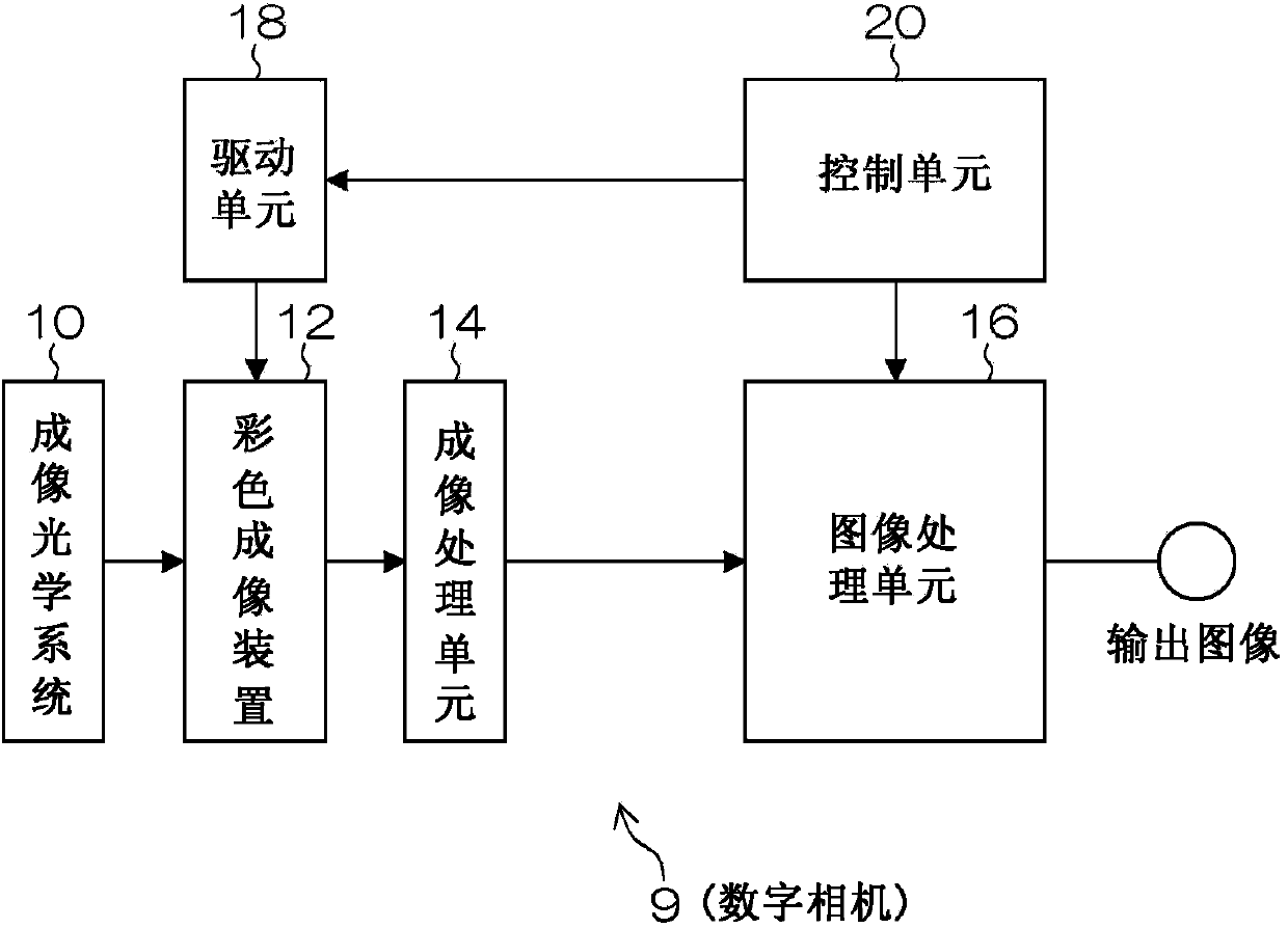
[0067] figure 1 It is a block diagram illustrating a digital camera 9 including a color imaging device according to the present invention. The digital camera 9 includes an imaging optical system 10, a color imaging device 12, an imaging processing unit 14, an image processing unit 16, a driving unit 18, and a control unit 20.

[0068] The imaging optical system 10 images an object, and an optical image for indicating an image of the object is formed on the light receiving surface of the color imaging device 12 (the color imaging device of the first embodiment).

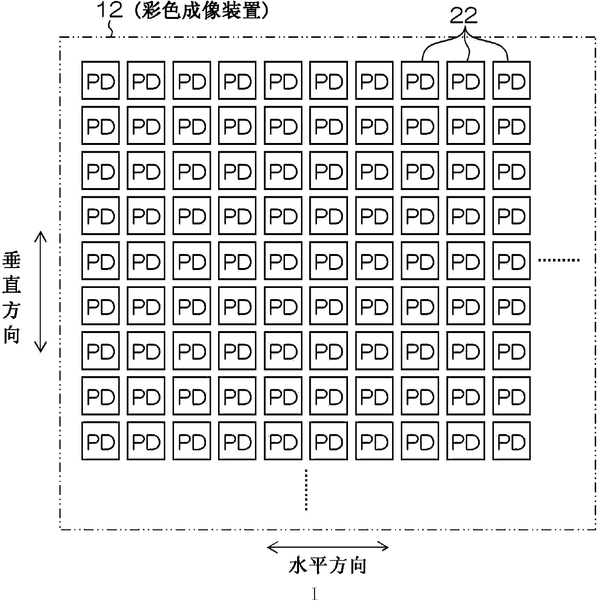
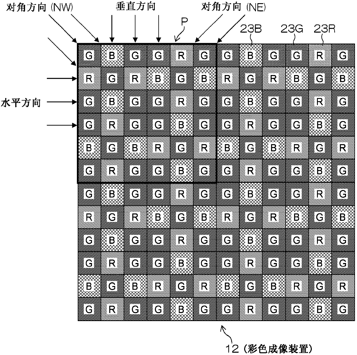
[0069] The color imaging device 12 is a so-called single-plate type color imaging device, which includes: a plurality of pixels formed using photoelectric conversion elements arranged (two-dimensional array) in the horizontal and vertical direct...


PUM


Abstract

A color filter array of a color image pick-up element (26) is configured by repeatedly disposing, in the horizontal and vertical directions, a base array pattern (P1) wherein RGB filters (23R, 23G, 23B) are arrayed in an array pattern of 8 x 12 pixels. The base array pattern (P1) is disposed in a matrix shape in the horizontal and vertical directions, and includes array A (27a) through array D (27d), which have an array pattern of 4 x 4 pixels. In each of the arrays (27a to 27d), G filters (23G) are arranged in a checker board pattern and so that the arrangement of the G filters (23G) is in a mirror-image relationship between adjacent arrays of the arrays (27a to 27d).

Description

Technical field [0001] The present invention relates to a color imaging device, and in particular to a color imaging device that can reduce the appearance of color moiré and achieve high resolution. Background technique [0002] In the single-plate type color imaging device, since a color filter of one color is provided on each pixel, each pixel has color information of only one color. Therefore, because the output image of the single-plate type color imaging device is a RAW image (mosaic image), a multi-channel image is obtained through processing (synchronization processing) for interpolating pixels of missing colors of surrounding pixels. In this case, there is a problem of reproduction characteristics of high-frequency image signals. Compared with imaging devices for black and white, in color imaging devices, jaggies are easily generated in captured images. Therefore, there is a problem in which it is important to realize high resolution by expanding the reproduction freque...

Claims


Application Information

Patent Timeline
Patent Type & Authority Applications(China)
IPC IPC(8): H04N9/07
CPCH04N9/646H04N9/045H04N25/134
Inventor 河合智行林健吉田中诚二
Owner FUJIFILM CORP
Why Eureka
Try Eureka