Traffic Signal Control System, Design Method and Special Equipment

Inactive Publication Date: 2013-01-31
HWYL HUBBL TECH DEV CO LTD IN BEIJING
View PDF5 Cites 32 Cited by
  • Summary
  • Abstract
  • Description
  • Claims
  • Application Information

AI Technical Summary

Benefits of technology

The patent text describes a method for improving the efficiency and safety of signals at intersections. The method involves finding a key path to minimize the time between the arrival of key traffic and its later arrival, selecting a preferable channelization scheme to reduce the minimum green interval, and reducing the start-up loss time of the traffic flow. These methods combined can result in a negative cycle loss time, meaning that the effective green time is larger than the cycle. This results in a more efficient and secure intersection, with increased traffic capacity and reduced delay time.

Problems solved by technology

Since the three constraints can not be determined accurately by all the typical signal control systems, there are disadvantages in the following four technical means.
The existing control design methods are completely ineffective in the case of negative cycle loss time.
Firstly, the road channelization is performed with great arbitrariness, since conventionally there is no specific numerical value index to appraise the road channelization.
Thus the minimum green interval is set to be too small, which is neither reasonable nor safe, leading to accident-proneness in the phase interval.
No literature can assure that a phase structure scheme therein is the best.
In addition, in these classic systems, it is not able to configure a countdown display and it is difficult to reduce the start-up lost time.
However, an estimation value which is very inaccurate is commonly used instead.

Method used


Image

  • Traffic Signal Control System, Design Method and Special Equipment
  • Traffic Signal Control System, Design Method and Special Equipment
  • Traffic Signal Control System, Design Method and Special Equipment

Examples


eighth embodiment

Further, in an eighth embodiment, the coordination signal control system for ground surface road network formed by multi-crossing. The present application provides a coordination signal control system for ground surface road network formed by multi-crossing, which includes the above mentioned traffic signal control system for the crossing, can ensure that the cycle loss time of each of the crossings keeps constant and can allow that each of the crossings doesn't need to have a minimum cycle so as to be able to have the same cycle needed to participate the coordination control.

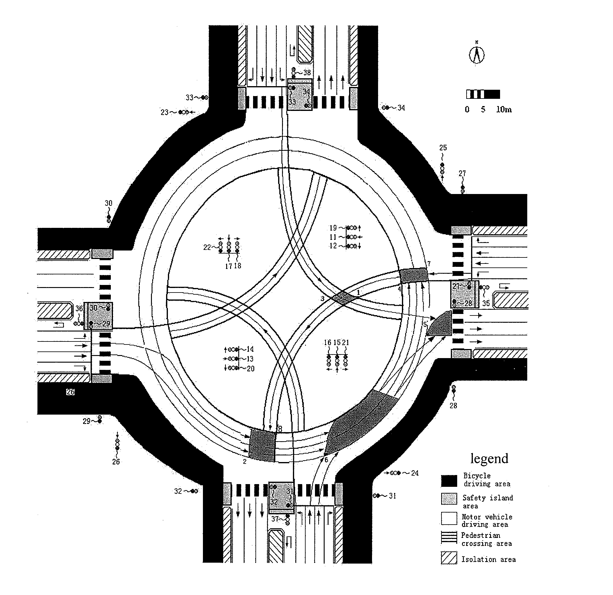
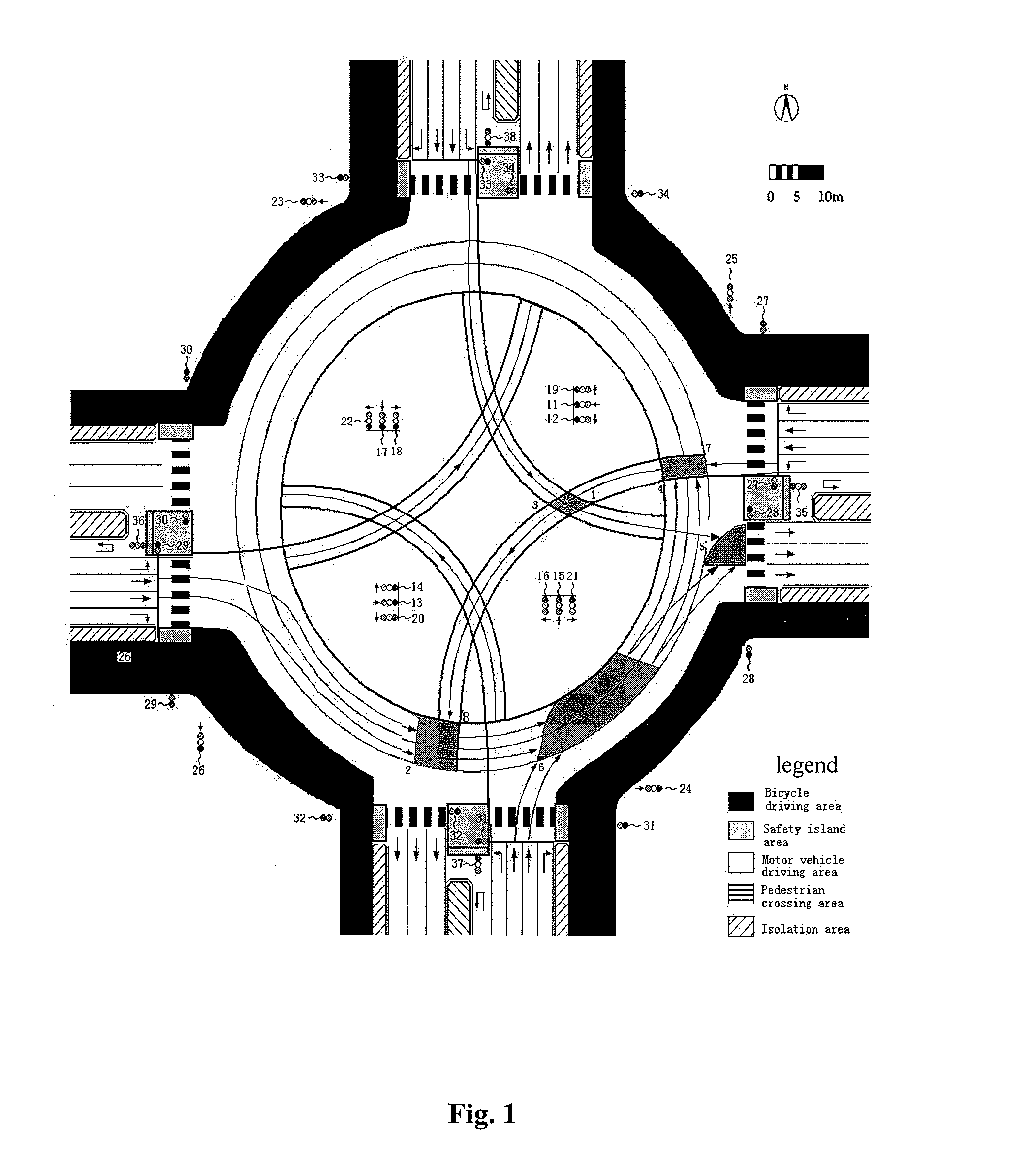
[0158]Although the description of the present application is for the cross intersection, the present application may be applied to other intersections. The traffic signal control system according to the present invention mainly includes: a signal controller, a signal display apparatus, and further includes a detector in the case of the dynamical adjusting scheme, which may be connected wirelessly or via a fiber...


PUM


Abstract

A traffic signal control method comprises confirming the shortest green light interval; confirming the conflict area of the different traffic flow and the key conflict point position according to the engineering design for road canalization; confirming the longest clear distance si(m) of the traffic tail unit of green light i and the shortest entry distance sj(m) of the traffic head unit of green light j in conflict with green light i; calculating the longest clear time Max{ti} of the traffic tail unit of green light i and the shortest entry time Min{tj} of the traffic head unit of green light j; calculating the shortest green light interval Iij=A+Max{ti}−Min{tj}; confirming the control scheme for the crossing according to the shortest green light interval and sending the control instruction to the traffic signal display device for displaying in real time according to the control scheme. A traffic signal control system and special equipment are also provided.

Description

CROSS REFERENCE TO RELATED APPLICATIONS[0001]This application is a 35 U.S.C. §371 national stage application of PCT / CN2010 / 076325 filed Aug. 25, 2010, which claims the benefit of Chinese Patent Application No. 201010191873.7 filed Jun. 4, 2010 and Chinese Patent Application No. 201020215719.4 filed Jun. 4, 2010, all of which are incorporated herein by reference in their entireties for all purposes.STATEMENT REGARDING FEDERALLY SPONSORED RESEARCH OR DEVELOPMENT[0002]Not applicable.FIELD OF THE INVENTION[0003]The present invention generally relates to the field of traffic information engineering and control, and in particular to a control system and design method for a traffic signal on an intersection and a special device.BACKGROUND OF THE INVENTION[0004]At a grade intersection, a conflict area is a space which traffic units in different flow directions have to pass. A critical point is the most dangerous point in the conflict area. The traffic units enter into the conflict area in t...

Claims


Application Information

Patent Timeline
IPC IPC(8): G08G1/00
CPCG08G1/07
Inventor WANG, QIANWANG, DAHAIYE, NAN
Owner HWYL HUBBL TECH DEV CO LTD IN BEIJING
Why Eureka
Try Eureka