
Iodine Fueled Plasma Generator System

a generator system and plasma technology, applied in the direction of machines/engines, transportation and packaging, cosmonautic vehicles, etc., can solve the problems of compromising storage density and high cost of x

Active Publication Date: 2013-01-31
BUSEK
View PDF3 Cites 17 Cited by
  • Summary
  • Abstract
  • Description
  • Claims
  • Application Information

AI Technical Summary

Benefits of technology

The patent describes a system for generating plasma using iodine fuel. The system includes a plasma generator, a storage vessel for iodine, a heating device, a propellant management subsystem, and a feedback control subsystem. The feedback control subsystem regulates the flow of iodine vapor to the plasma generator based on discharge current, temperature, and pressure. The system uses a thermal throttle to regulate the flow rate of iodine vapor by changing its viscosity or phase. The shape of the storage vessel and accumulator vessel may be non-symmetrical or conformal to maximize storage density. The system may also include an accumulator vessel to transfer iodine vapor. The technical effect of the patent is to provide a system for efficient and controlled plasma generation using iodine fuel.

Problems solved by technology

Xe is expensive and must be stored at high pressure in large cylindrically symmetric shaped high strength storage tanks which can compromise storage density.
Thus, the '363 patent does not provide feedback to regulate the flow rate of the iodine gas to the thruster which may improve performance.

Method used


Image

  • Iodine Fueled Plasma Generator System
  • Iodine Fueled Plasma Generator System
  • Iodine Fueled Plasma Generator System

Examples


Embodiment Construction

[0020]Aside from the preferred embodiment or embodiments disclosed below, this invention is capable of other embodiments and of being practiced or being carried out in various ways. Thus, it is to be understood that the invention is not limited in its application to the details of construction and the arrangements of components set forth in the following description or illustrated in the drawings. If only one embodiment is described herein, the claims hereof are not to be limited to that embodiment. Moreover, the claims hereof are not to be read restrictively unless there is clear and convincing evidence manifesting a certain exclusion, restriction, or disclaimer.

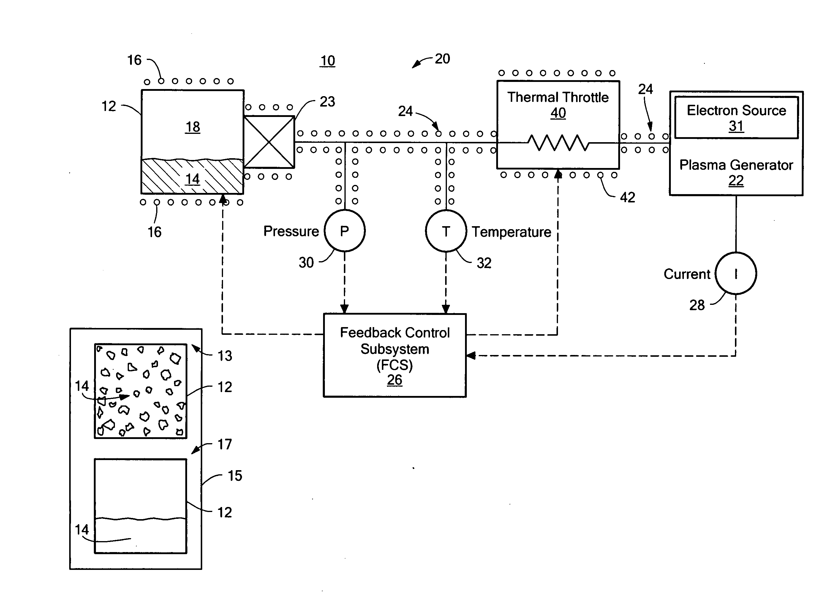
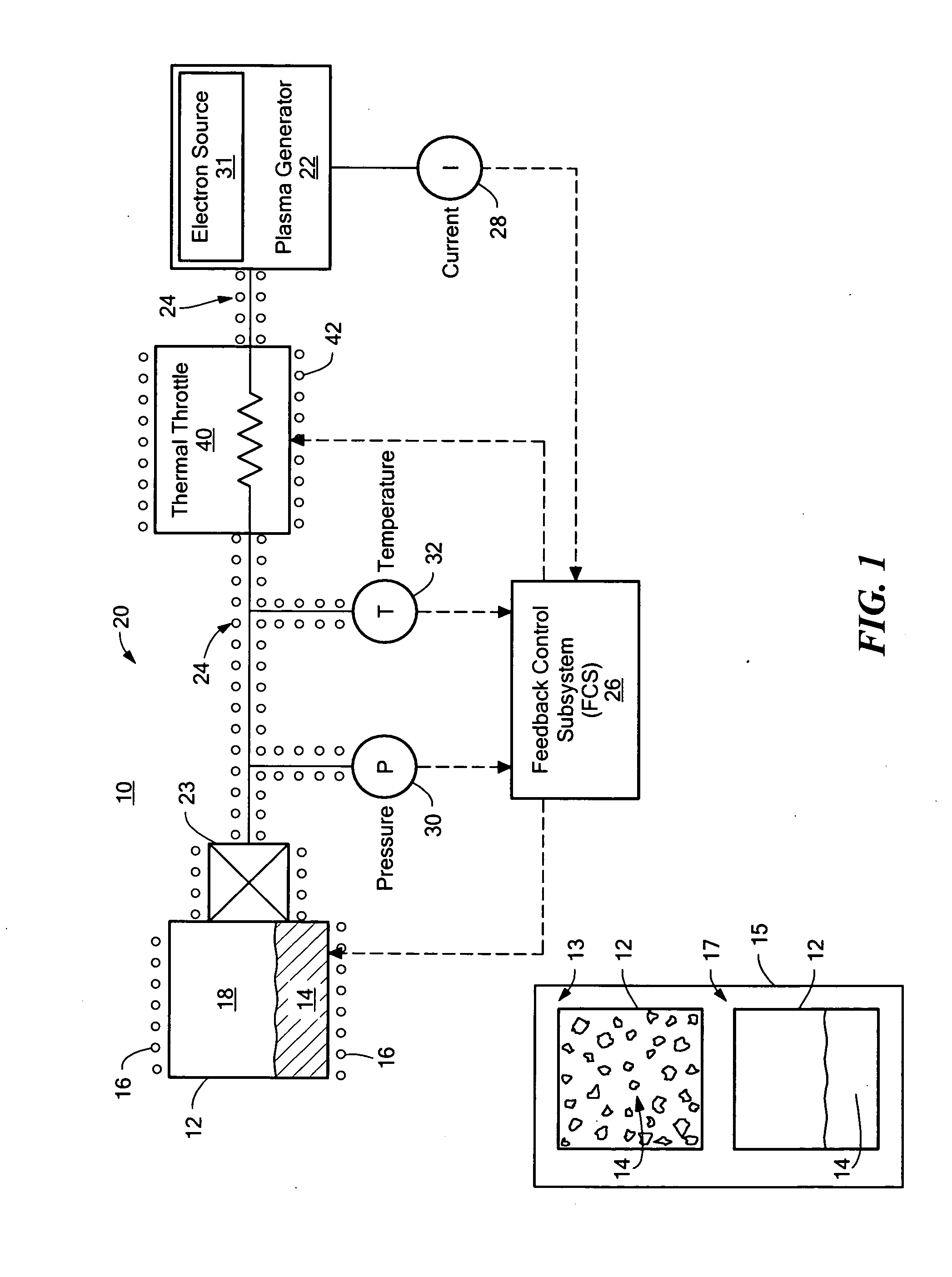
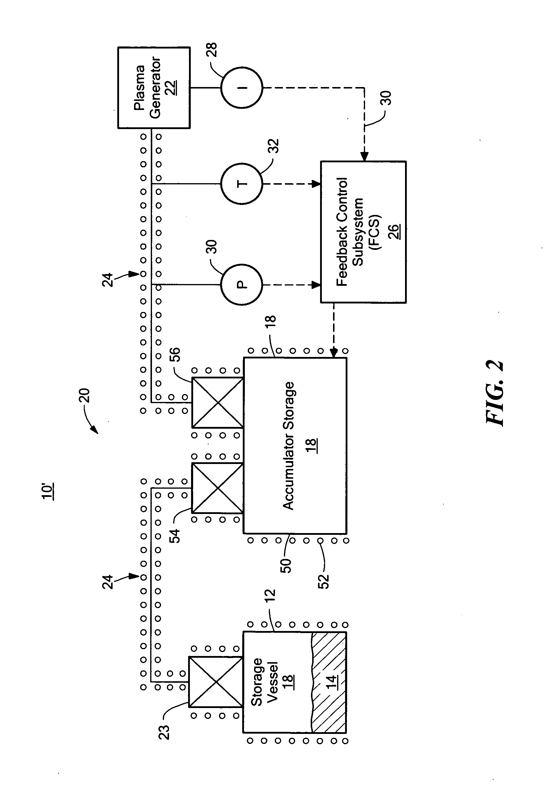
[0021]There is shown in FIG. 1, one embodiment of iodine fueled plasma generator system 10 of this invention. System 10 includes plasma generator 22 which may include electron source 31. System 10 also includes at least one storage vessel, e.g., storage vessel 12, configured to store condensed phased iodine 14 therein. In o...


PUM


Abstract

An iodine fueled plasma generator system includes a plasma generator. At least one storage vessel is configured to store condensed phase iodine therein. A heating device proximate to the storage vessel is configured to create iodine vapor from the condensed phase iodine. A propellant management subsystem is configured to deliver the iodine vapor to the plasma generator. A feedback control subsystem is responsive to one or more of plasma generator discharge current, the pressure of the iodine vapor, and / or the temperature of the iodine vapor configured to regulate the flow rate of the iodine vapor to the plasma generator.

Description

RELATED APPLICATIONS[0001]This application claims benefit of and priority to U.S. Provisional Application Ser. No. 61 / 574,123 filed Jul. 28, 2011 under 35 U.S.C. §§119, 120, 363, 365, and 37 C.F.R. §1.55 and §1.78 incorporated herein by this reference.GOVERNMENT RIGHTS[0002]This invention was made with U.S. Government support under Contract No's. FA9453-10-M-0070 and FA9453-11-C-0017 awarded by the Air Force Research Laboratory (AFRL), and Contract No. FA8601-10-P-0510 awarded by the Air Force Institute of Technology. The Government may have certain rights in the subject invention.FIELD OF THE INVENTION[0003]This invention relates to an iodine fueled plasma generator system.BACKGROUND OF THE INVENTION[0004]Some conventional plasma generators, such as electrostatic thrusters, electromagnetic thrusters, and the like, operate almost exclusively on the noble gas Xenon (Xe). Xe is expensive and must be stored at high pressure in large cylindrically symmetric shaped high strength storage ...

Claims


Application Information

Patent Timeline
Patent Type & Authority Applications(United States)
IPC IPC(8): H05H1/46H05H1/24
CPCF03H1/0012B64G1/405B64G1/402B64G1/413
Inventor SZABO, JR., JAMES J.POTE, BRUCEPAINTAL, SURJEETROBIN, MICHAELHRUBY, VLADIMIR
Owner BUSEK
Learn More