
Rail vehicle consist speed control system and method

a technology of speed control system and rail vehicle, applied in vehicle position/course/altitude control, process and machine control, instruments, etc., can solve problems such as unnecessary fuel consumption, slow orders, and delays, and achieve slow orders

Active Publication Date: 2013-01-17
GE GLOBAL SOURCING LLC
View PDF11 Cites 24 Cited by
  • Summary
  • Abstract
  • Description
  • Claims
  • Application Information

AI Technical Summary

Benefits of technology

This patent describes a system, method, and device for controlling a rail vehicle consist that can navigate a rail system. The system includes sensors that capture environmental data about the rail system and use that data to control the vehicle's tractive effort (the amount of effort provided by the vehicle's wheels to move the vehicle along the track) over a specific portion of the track. This allows for more efficient and effective control of the vehicle's speed and performance. The system also includes a processor and memory to store and analyze the environmental data, and a control module to communicate the appropriate control signals to the vehicle's driver for safe and successful operation. Overall, this technology helps improve the efficiency and safety of rail vehicles in real-life scenarios.

Problems solved by technology

Furthermore, slow orders, which comprise temporary speed restrictions, may be issued for an entire rail system (e.g., a lower speed on hot days due to a danger of track buckling) or a portion of the rail system (e.g., due to workmen near a particular section of track).
In addition, unnecessary braking also may result in unnecessary fuel consumption.
Likewise, slow orders may sometimes be generated based on environmental conditions that no longer exist or do not exist at the location of the train.
As a result, a train may travel at a slower speed than necessary, which also may result in fuel waste and increase the duration of the trip.

Method used


Image

  • Rail vehicle consist speed control system and method
  • Rail vehicle consist speed control system and method
  • Rail vehicle consist speed control system and method

Examples


Embodiment Construction

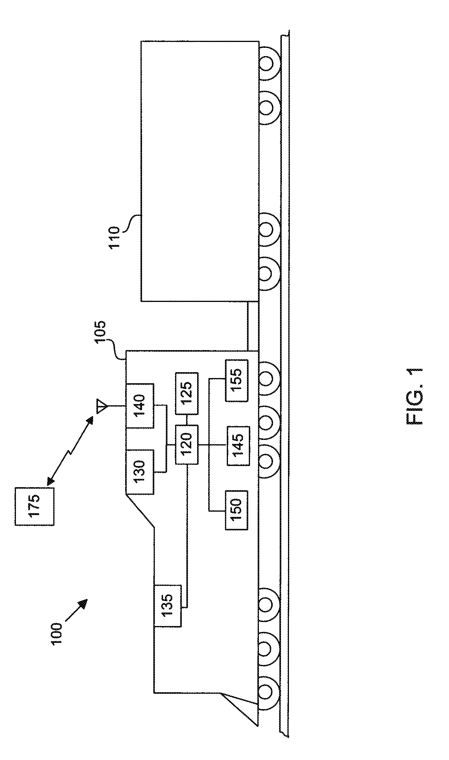
[0018]As used herein, the term “consist” is meant to refer to a group of vehicles mechanically linked to travel together along a route. Thus, the term “consist” may be applicable when referring to various types of systems including, but not limited to, marine vessels, off-highway vehicles, agricultural vehicles, mining vehicles, trains, and / or construction equipment that operate together so as to provide propulsion and / or braking capability. Therefore, even though the term rail vehicle consist is used herein in regards to certain illustrative embodiments, the term “consist” may also apply to other powered systems. In addition, as used herein the term “rail vehicle consist” is meant to include any and all rail vehicles such as, for example, trains and mining carts.

[0019]Furthermore though the example embodiments are disclosed with respect to a rail vehicle consist, such disclosures are not to be considered limiting. Embodiments of the present invention may be applicable to other powe...


PUM


Abstract

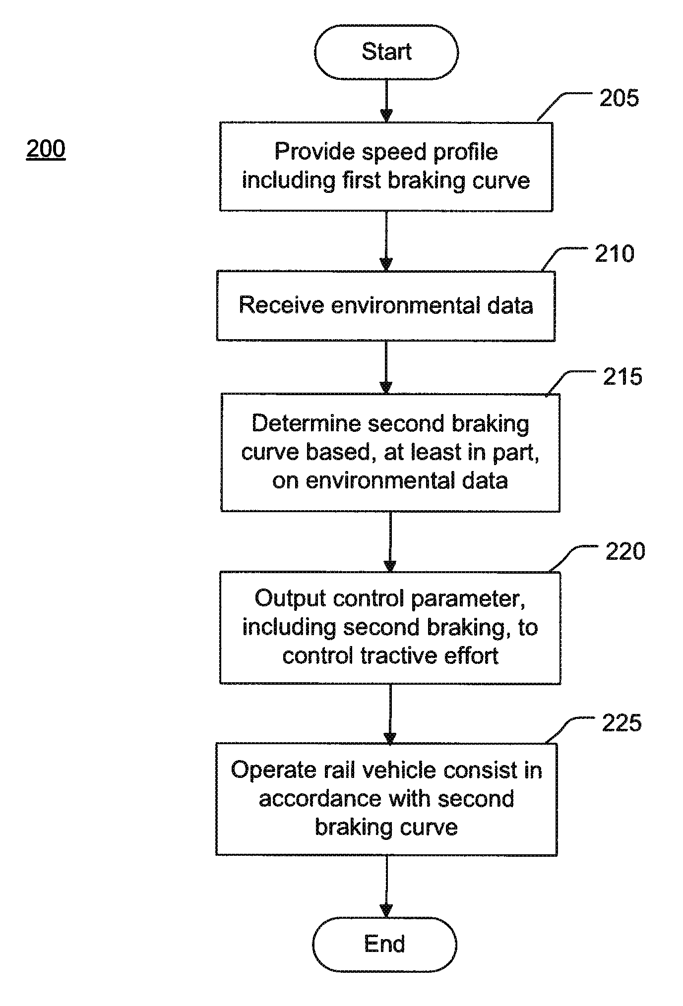
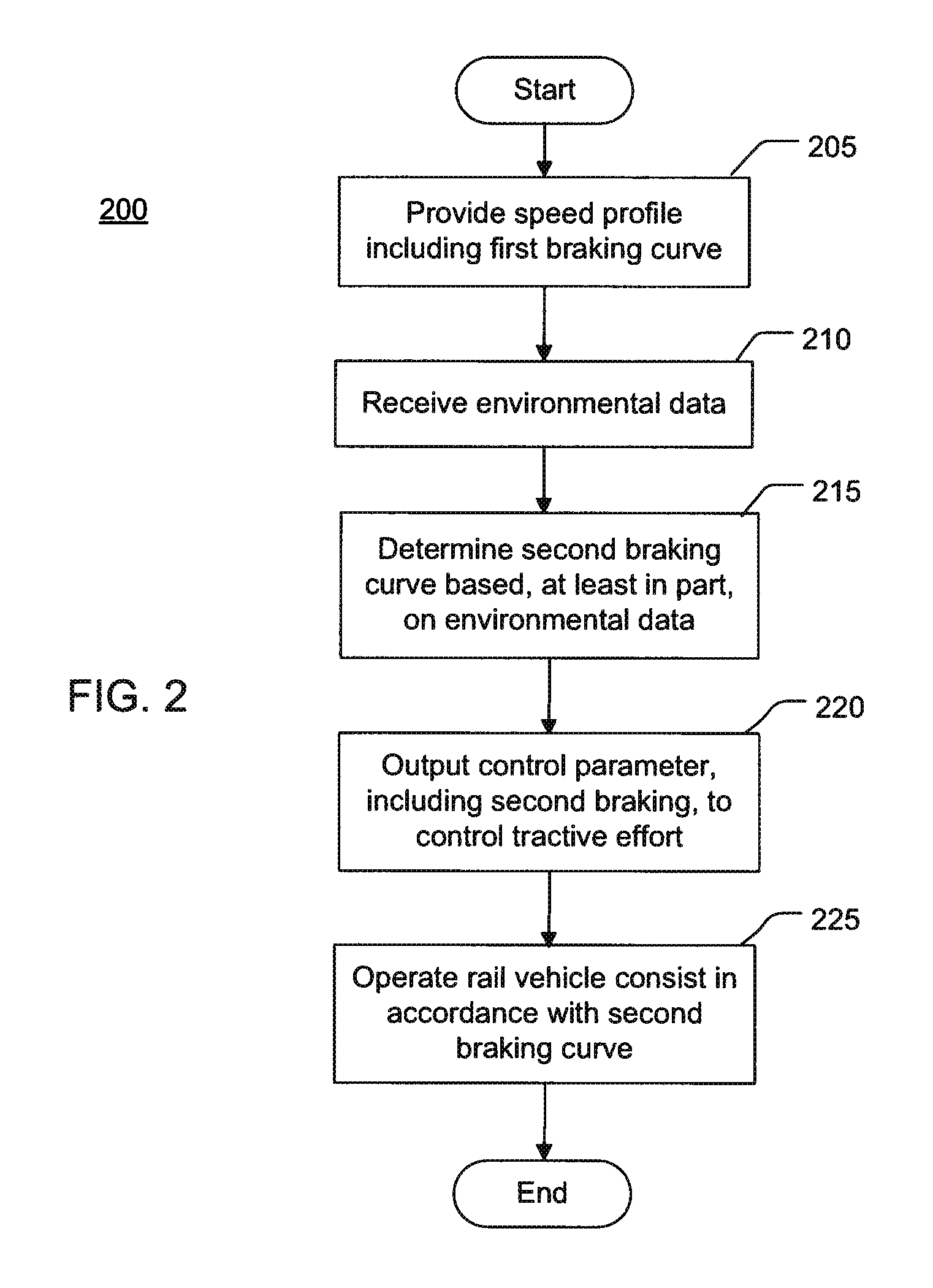
A system, method and device for controlling a rail vehicle consist configured to traverse a rail system is provided. In one embodiment, the system may include a second module configured to receive environmental data from a first module having one or more sensors, wherein the environmental data is indicative of one or more environmental conditions for a portion of the rail system; wherein the second module is further configured to conduct an assessment of the environmental data in relation to a first control parameter; the second module is further configured to communicate one or more control signals of one of the first control parameter or a different, second control parameter based on the assessment; each of the first and second control parameters relates to controlling tractive effort of the rail vehicle consist over the portion of the rail system; and the second module is further configured to communicate the one or more control signals to a third module for control of the rail vehicle consist.

Description

[0001]Embodiments of the invention relate to consists. Other embodiments relate to controlling the speed of a rail vehicle consist.BACKGROUND[0002]One aspect of rail vehicle safety is ensuring that the rail vehicles, such as trains, do not exceed maximum allowable speeds. Maximum speed limits may be dictated for the rail vehicle throughout an entire rail system. Some sections of track may have different maximum speed limits than others. Furthermore, slow orders, which comprise temporary speed restrictions, may be issued for an entire rail system (e.g., a lower speed on hot days due to a danger of track buckling) or a portion of the rail system (e.g., due to workmen near a particular section of track).[0003]To reduce fuel consumption and emissions, some trains and other powered systems may use an on-board energy management system, fuel saving system, speed control system, or other train control system. On-board energy management systems, for example, may incorporate (or otherwise uti...

Claims


Application Information

Patent Timeline
Patent Type & Authority Applications(United States)
IPC IPC(8): G05D1/02
CPCB61L3/008B61L3/006B61L15/0058B61L15/0062
Inventor COOPER, JAREDPELTZ, DAVIDBALLESTY, DANIELBREMMER, ROBERTBRADSHAW, LINDSEYCHEN, YI
Owner GE GLOBAL SOURCING LLC
Learn More