
Sound Processing Apparatus

a technology of sound processing and sound source, which is applied in the field of sound processing apparatus, can solve the problems of high accuracy and difficulty in accurately separating (clustering) the mixed sound of a plurality of sounds by respective sound sources

Inactive Publication Date: 2013-01-10
YAMAHA CORP
View PDF0 Cites 16 Cited by
  • Summary
  • Abstract
  • Description
  • Claims
  • Application Information

AI Technical Summary

Benefits of technology

The present invention relates to a sound processing apparatus that can accurately separate and process sound signals. It uses a matrix factorization unit to generate a first coefficient matrix, a second basis matrix, and a second coefficient matrix based on constraints that decrease the similarity between the first basis matrix and the second basis matrix. This prevents the omission of a sound from a sound signal after being separated. The second basis matrix is not correlated to the acquired first basis matrix, which ensures the separation of the first sound source and the second sound source at a target accuracy. The matrix factorization unit can repetitively compute an update formula to generate the first coefficient matrix, the second basis matrix, and the second coefficient matrix with high accuracy while restraining partial omission of the sounds. The invention can be used in various sound processing applications such as sound effects separation, sound source separation, and sound enhancement.

Problems solved by technology

However, the technologies of Non-Patent Reference 1 and Non-Patent Reference 2 have problems in that it is difficult to accurately separate (cluster) the plurality of basis vectors h of the basis matrix H and the plurality of coefficient vectors u of the coefficient matrix U by respective sound sources, and sounds of a plurality of sound sources may coexist in one basis vector h of the basis matrix H. Accordingly, it is difficult to separate a mixed sound of a plurality of sounds by respective sound sources with high accuracy.

Method used


Image

  • Sound Processing Apparatus
  • Sound Processing Apparatus
  • Sound Processing Apparatus

Examples


first embodiment

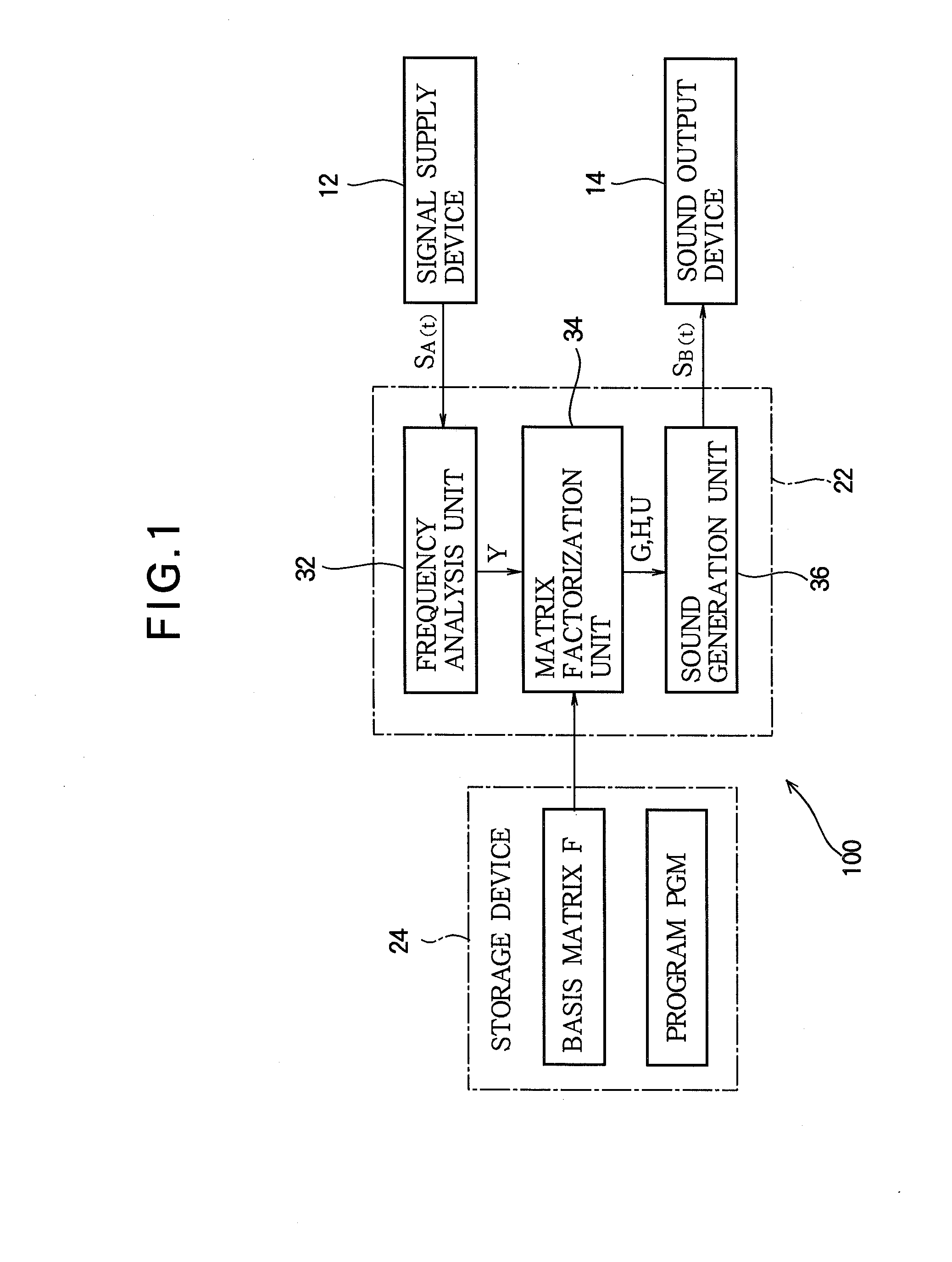
[0028]FIG. 1 is a block diagram of a sound processing apparatus 100 according to a first embodiment of the present invention. Referring to FIG. 1, the sound processing apparatus 100 is connected to a signal supply device 12 and a sound output device 14. The signal supply device 12 supplies a sound signal SA(t) to the sound processing apparatus 100. The sound signal SA(t) represents the time waveform of a mixed sound composed of sounds (musical tones or voices) respectively generated from different sound sources. Hereinafter, a known sound source from among a plurality of sound sources which generate sounds constituting the sound signal SA(t) is referred to as a first sound source and a sound source other than the first sound source is referred to as a second sound source. When the sound signal SA(t) is composed of sounds generated from two sound sources, the second sound source corresponds to the sound source other than the first sound source. When the sound signal SA(t) is composed...

second embodiment

[0058]A second embodiment of the invention will now be described. In each embodiment illustrated below, elements whose operations or functions are similar to those of the first embodiment will be denoted by the same reference numerals as used in the above description and a detailed description thereof will be omitted as appropriate.

[0059]In the first embodiment, the basis vector h[d] of the basis matrix H computed by the matrix factorization unit 34 may become equal to the basis vector f[k] of the known basis matrix F because the correlation between the basis matrix F of the first sound source and the basis matrix H of the second sound source is not confined. When the basis vector h[d] corresponds to the basis vector f[k], one of the coefficient vector g[k] of the coefficient matrix G and the coefficient vector u[d] of the coefficient matrix U converges into a zero vector in order to establish expression (2). However, a sound component of the first sound source, which corresponds to...

third embodiment

[0072]In the evaluation function J of expression (3A) exemplified in the second embodiment, the values of the error term ∥Y−FG−HU∥Fr2 and correlation term ∥FTH∥Fr2 may be considerably different from each other. That is, degrees of contribution of the error term and correlation term to increase / decrease of the evaluation function J can remarkably differ from each other. For example, when the error term is remarkably larger than the correlation term, the evaluation function J is sufficiently reduced if the error term decreases, and thus there is a possibility that the correlation term is not sufficiently reduced. Similarly, the error term may not sufficiently decrease if the correlation term is considerably larger than the error term.

[0073]Accordingly, in the third embodiment, the error term and the correlation term of the evaluation function J approximate each other. Specifically, an evaluation function K represented as the following expression (3B), which is obtained by adding a pre...


PUM


Abstract

In a sound processing apparatus, a matrix factorization unit acquires a non-negative first basis matrix including a plurality of basis vectors that represent spectra of sound components of a first sound source, and acquires an observation matrix that represents time series of a spectrum of a sound signal corresponding to a mixed sound of the first sound source and a second sound source different from the first sound source. The matrix factorization unit generates a first coefficient matrix, a second basis matrix and a second coefficient matrix from the observation matrix by non-negative matrix factorization using the first basis matrix. A sound generation unit generates either of a sound signal according to the first basis matrix and the first coefficient matrix or a sound signal according to the second basis matrix and the second coefficient matrix.

Description

BACKGROUND OF THE INVENTION[0001]1. Technical Field of the Invention[0002]The present invention relates to a technology for separating sound signals by sound sources.[0003]2. Description of the Related Art[0004]A sound source separation technology for separating a mixed sound of a plurality of sounds respectively generated from different sound sources by the respective sound sources has been proposed. For example, Non-Patent Reference 1 and Non-Patent Reference 2 disclose an unsupervised sound source separation using non-negative matrix factorization (NMF).[0005]In the technologies of Non-Patent Reference 1 and Non-Patent Reference 2, an observation matrix Y that represents the amplitude spectrogram of an observation sound corresponding to a mixture of a plurality of sounds is decomposed into a basis matrix H and a coefficient matrix U (activation matrix), as shown in FIG. 6 (Y≈HU). The basis matrix H includes a plurality of basis vectors h that represent spectra of components inclu...

Claims


Application Information

Patent Timeline
Patent Type & Authority Applications(United States)
IPC IPC(8): H04R5/00
CPCG10L21/028
Inventor YAGI, KOSUKESARUWATARI, HIROSHITAKAHASHI, YU
Owner YAMAHA CORP
Learn More