
Power management in transcranial magnetic stimulators

a technology of transcranial magnetic stimulation and power management, which is applied in the direction of magnetotherapy, magnetotherapy using coils/electromagnets, magnetotherapy, etc., can solve the problems of capacitors presenting a large load to high-voltage supplies, unable to easily meet conventional building wiring, and unable to regulate power factor or peak load

Inactive Publication Date: 2013-01-03
RIO GRANDE NEUROSCI
View PDF7 Cites 34 Cited by
  • Summary
  • Abstract
  • Description
  • Claims
  • Application Information

AI Technical Summary

Benefits of technology

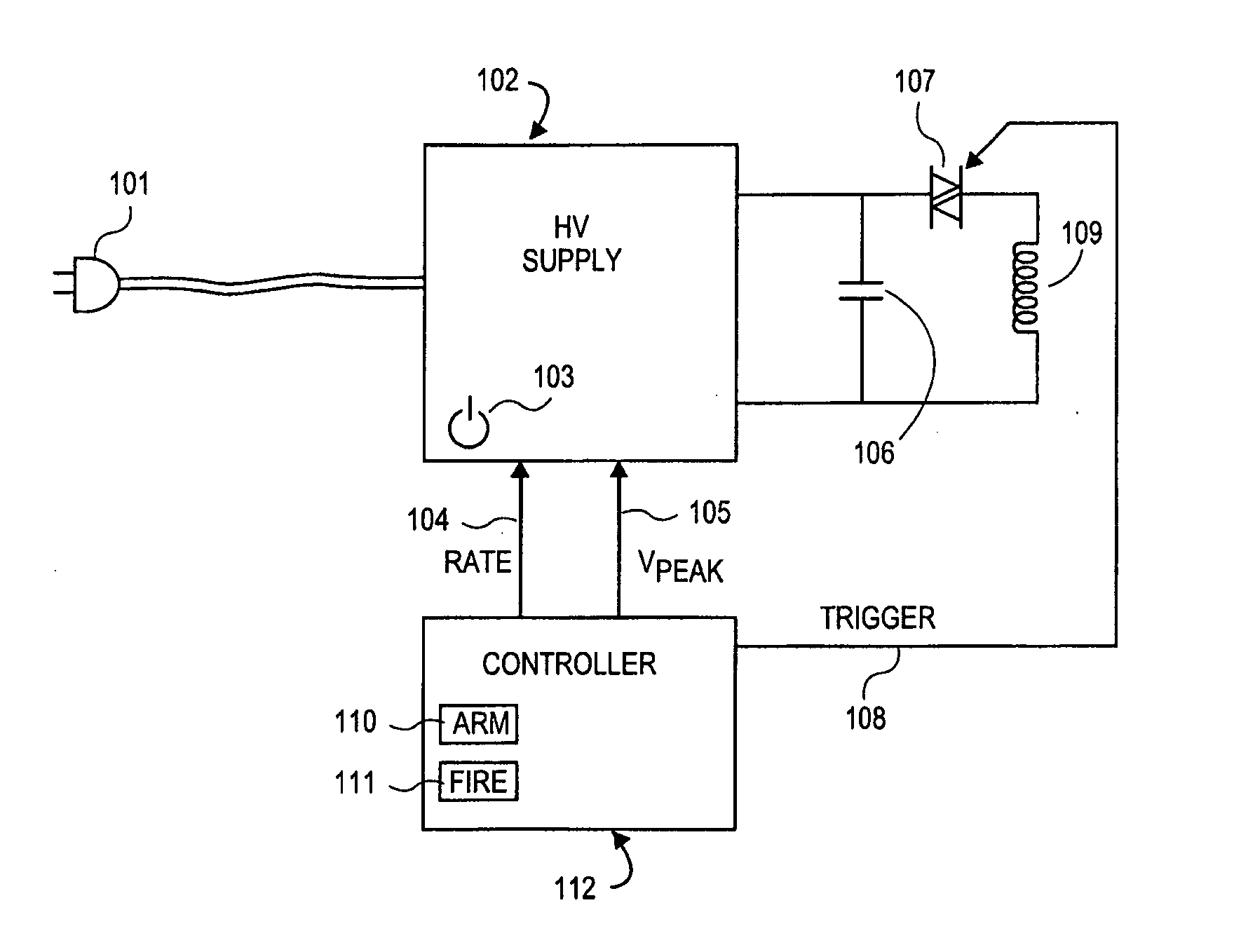
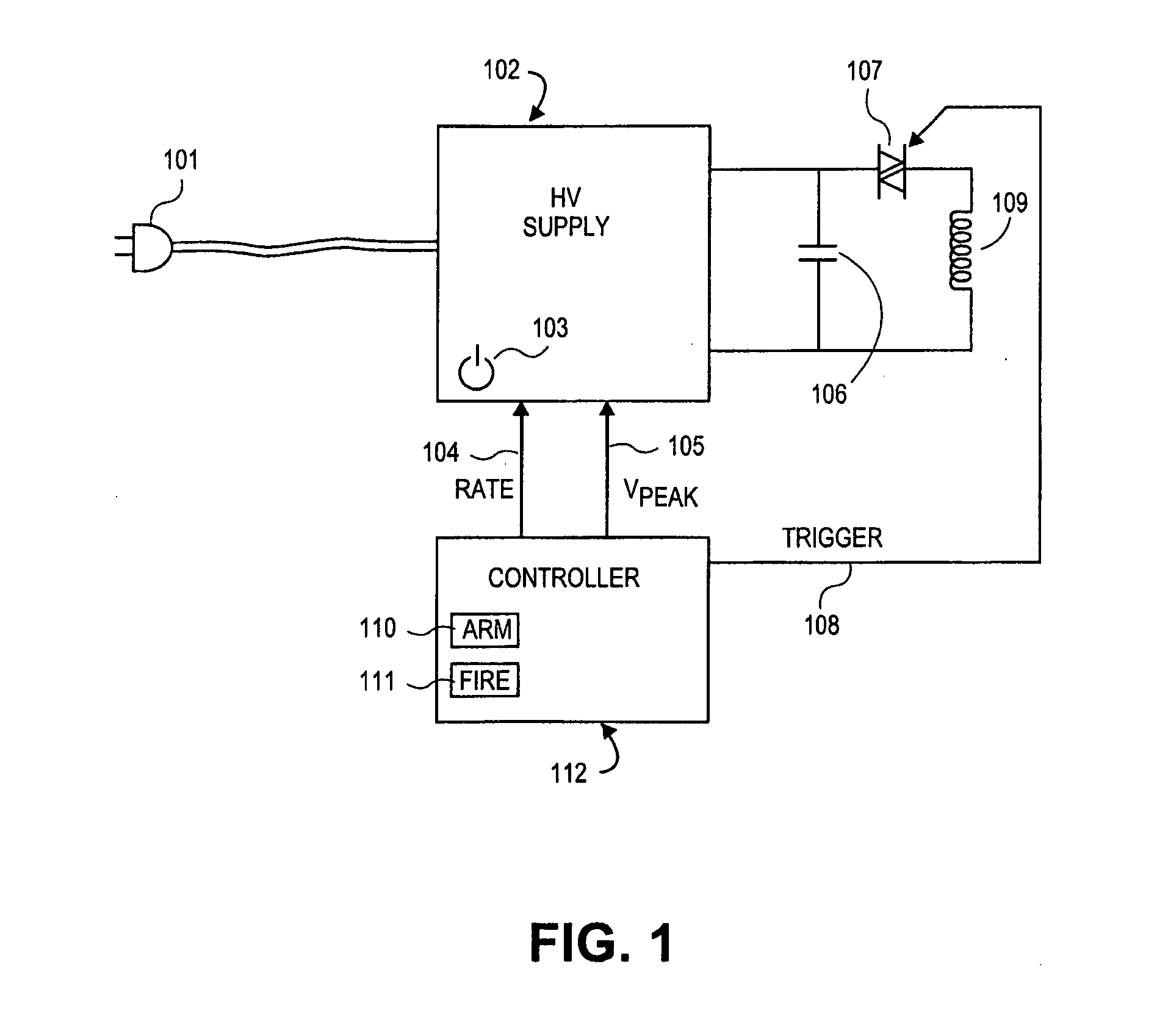
The present invention relates to systems and methods for providing electrical power to transcranial magnetic stimulation (TMS) systems. The technical effect of the invention is to provide a magnetic stimulator that presents less supply ripple, which means its instantaneous power demand is much closer to its average power demand. This makes it practical to run several stimulators and coils off the same AC line. The invention also includes a method for regulating the power factor and peak load demanded by the TMS system.

Problems solved by technology

Multi-coil repetitive Transcranial Magnetic Stimulation (rTMS) presents significant power demands that are not easily met by conventional building wiring.
Because each stimulator draws a large surge of power after each discharge, instantaneous power demand on the AC line spikes well above the average demand, resulting in the need to dedicate one or more AC circuits to each stimulator.
Once charge is dumped and resonance ceases (or the switch is opened), the capacitor presents a large load to the high voltage supply.
This solution is limited in that it does little to regulate the power factor or the peak load demanded by the stimulator.
Batteries have relatively high effective series resistance as compared to capacitors, and thus are not ideally suited for providing rapid bursts of very high current required by a TMS coil.

Method used


Image

  • Power management in transcranial magnetic stimulators
  • Power management in transcranial magnetic stimulators
  • Power management in transcranial magnetic stimulators

Examples


Embodiment Construction

[0015]The systems and methods described herein are directed to power supplies and power management for transcranial magnetic stimulation systems.

[0016]In one aspect, we provide a TMS system with a programmable high voltage power supply that charges the capacitor at a constant current until it reaches a predefined voltage or total stored energy:

E=CV22orE=QV2

[0017]where V is the voltage across the capacitor of capacitance C, and Q is the stored charge in the capacitor at voltage V.

[0018]Thus to compute the stored energy one must measure voltage V and either capacitance C of the capacitor or current during the charge cycle.

[0019]In another aspect, a multi-coil stimulator consists of one high-voltage supply with several discharge capacitors multiplexed to it via electronic switches and or diodes. There may be passive filtering elements to help manage load spikes between the capacitors and the supply, and snubbers to protect the switches from voltage spikes that arise from rapid switchin...


PUM


Abstract

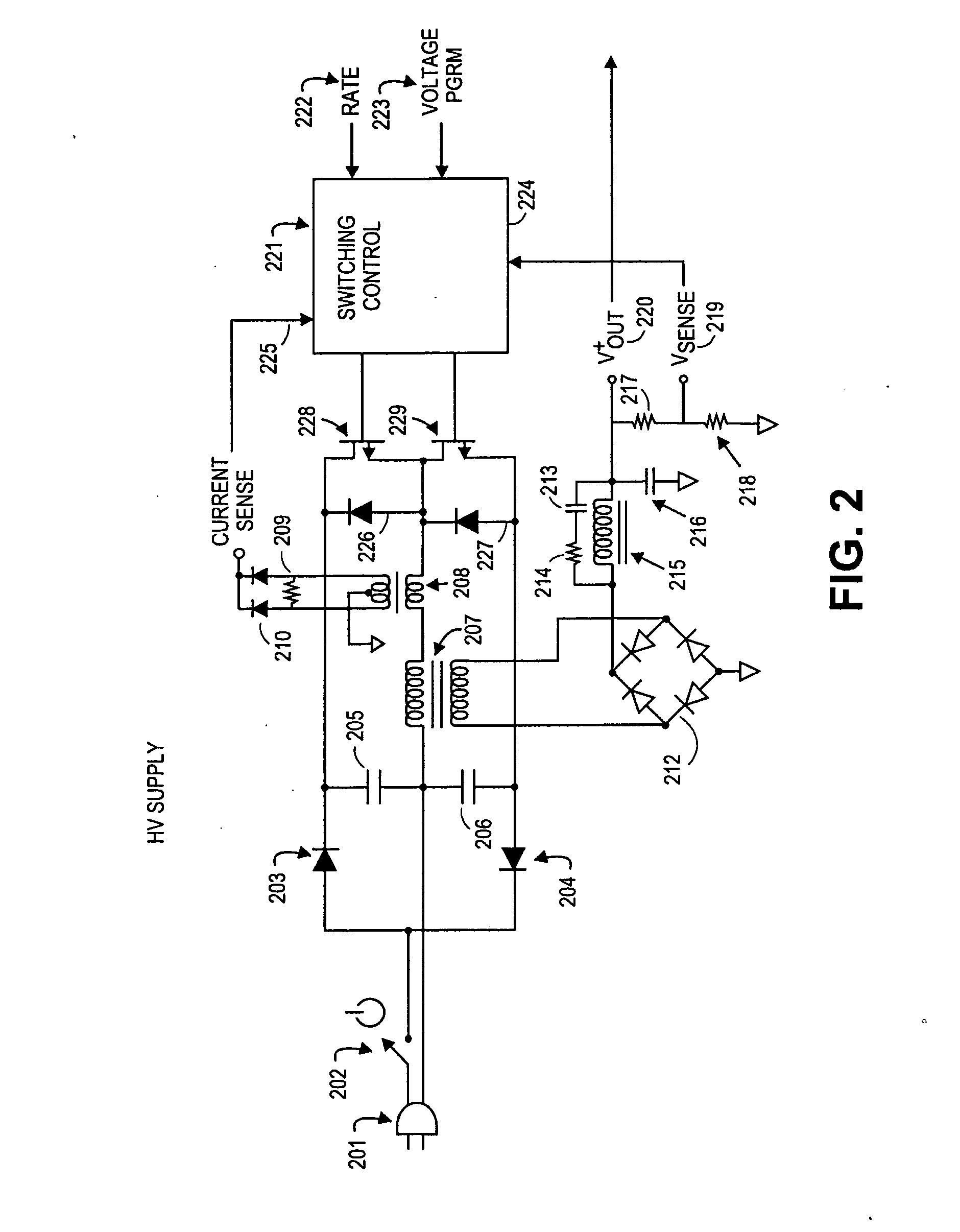
A system for supplying high voltage direct current for Transcranial Magnetic Stimulation (TMS) devices under program control features a rate input that commands the power supply to charge the discharge capacitors at a fixed rate until a programmed target voltage is achieved. This reduced demand spikes to the AC line when operating the TMS device, and may allow the TMS device to operate from a lower-rated AC circuit than would otherwise be possible.

Description

INCORPORATION BY REFERENCE[0001]All publications, including patents and patent applications, mentioned in this specification are herein incorporated by reference in their entirety to the same extent as if each individual publication was specifically and individually indicated to be incorporated by reference.FIELD OF THE INVENTION[0002]The present invention relates to systems and methods for providing electrical power to transcranial magnetic stimulation (TMS) systems.BACKGROUND OF THE INVENTION[0003]Multi-coil repetitive Transcranial Magnetic Stimulation (rTMS) presents significant power demands that are not easily met by conventional building wiring. A single Magstim Rapid®, for example, may require two 20 Amp circuits to power a single coil. Because each stimulator draws a large surge of power after each discharge, instantaneous power demand on the AC line spikes well above the average demand, resulting in the need to dedicate one or more AC circuits to each stimulator.[0004]A con...

Claims


Application Information

Patent Timeline
Patent Type & Authority Applications(United States)
IPC IPC(8): A61N2/04
CPCA61N2/02A61N2/006
Inventor SADLER, JOHN W.
Owner RIO GRANDE NEUROSCI
Learn More