
Optical device and signaling and/or lighting system

a technology of optical devices and signals, applied in the direction of fiber light guides, transportation and packaging, light and heating equipment, etc., can solve the problems of insufficient overall effectiveness of devices, and insufficient homogeneity of illumination on the exit fa

Active Publication Date: 2013-01-03
VALEO VISION SA
View PDF4 Cites 27 Cited by
  • Summary
  • Abstract
  • Description
  • Claims
  • Application Information

AI Technical Summary

Benefits of technology

The invention solves the problems with current techniques and allows for better design flexibility. It also allows for the second light guide to be placed at the rear of the prolongation, allowing for complete design customization.

Problems solved by technology

The overall effectiveness of the device, that is to say the luminous power of the light exiting the guide relative to the luminous power of the light entering the guide, is not optimal.
It is also noted that the homogeneity of the illumination on the exit face is not optimal, especially if the light guide is highly arced;or a system for coupling the luminous sources is put in place in an upstream part of the path of the rays, which coupling system induces consequent losses in practice.

Method used


Image

  • Optical device and signaling and/or lighting system
  • Optical device and signaling and/or lighting system
  • Optical device and signaling and/or lighting system

Examples


Embodiment Construction

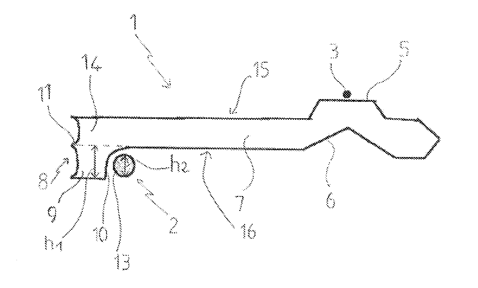
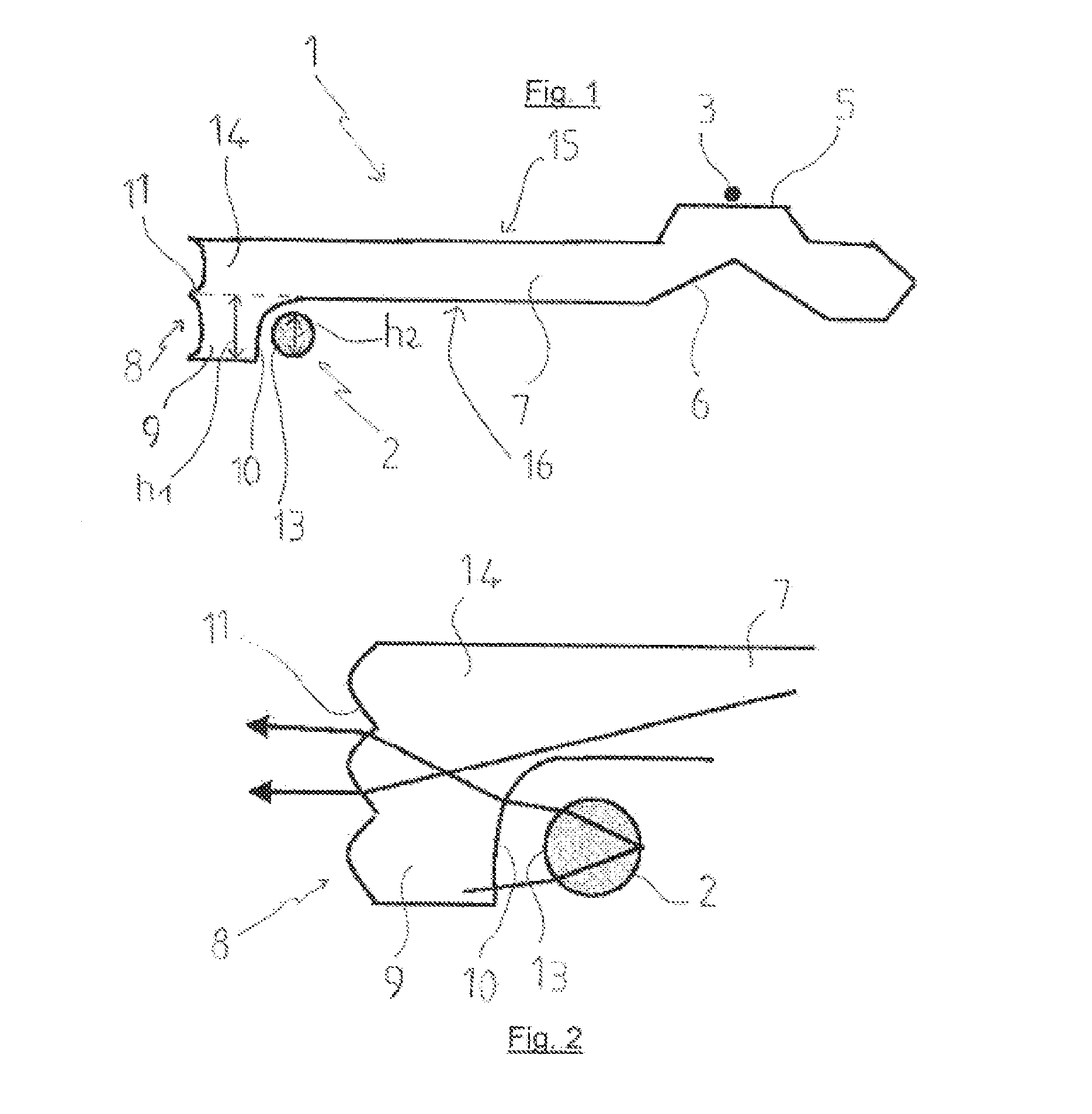
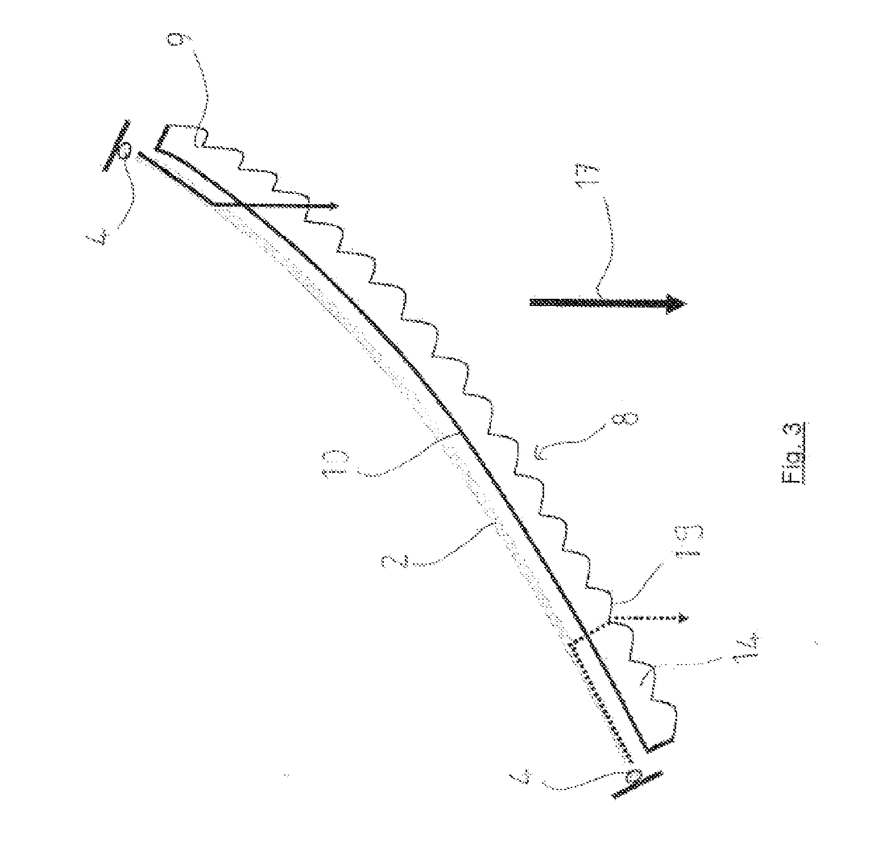
[0036]In a general manner, the present invention can use luminous sources of the light-emitting diode type also commonly called LEDs. In particular, these LEDs may be furnished with at least one microchip able to emit light whose intensity and color are tailored to the lighting and / or signaling function to be carried out. For example, a first luminous source can comprise at least one LED for achieving lighting in amber light for a change-of-direction flashing indicator light function. Moreover a second light source can comprise at least one white light LED for achieving a daytime lighting function. The number of LEDs is, however, not limiting of the invention, nor even the number of functions that may be implemented by the overall system of the invention. Moreover, the term luminous source is understood here as a set of at least one elementary source such as an LED able to produce a flux leading to the generation at the exit of the device of the invention of an exit flux fulfilling ...


PUM


Abstract

An optical device comprising an exit portion furnished with an exit face and designed to emit, through the exit face, light rays emanating from a first luminous source and from a second luminous source, characterized by the fact that it comprises a first light guide configured to propagate the light rays emanating from the first luminous source toward the exit portion and a second light guide configured to propagate the light rays emanating from the second source toward the exit portion. A preferential application is the field of lighting equipment for motor vehicles.

Description

CROSS-REFERENCE TO RELATED APPLICATIONS[0001]This application claims priority to French Application No. 1155857 filed Jun. 30, 2011, which application is incorporated herein by reference and made a part hereof.BACKGROUND OF THE INVENTION[0002]1. Field of the Invention[0003]The present invention pertains especially to an optical device and to a lighting and / or signaling system. A preferred application relates to the automobile industry, for vehicle equipment.[0004]2. Description of the Related Art[0005]In the field of optical devices for vehicles, the most conventional techniques consist in carrying out separately the various desired lighting or signaling functions such as: full beam headlight, dipped beam headlight, change-of-direction indicator light or else for example daytime lighting also referred to by its English acronym DRL (Day Running Light).[0006]With the general aim of improving the bulkiness and the visual rendition of luminous systems, there exists in the prior art, opt...

Claims


Application Information

Patent Timeline
Patent Type & Authority Applications(United States)
IPC IPC(8): B60Q1/00B60Q1/34
CPCF21S48/115F21S48/1241F21S48/215F21S48/2237G02B6/001F21S48/2262F21S48/2268F21S48/2281F21S48/2243F21S41/141F21S41/24F21S43/14F21S43/237F21S43/239F21S43/243F21S43/245F21S43/249
Inventor DE LAMBERTERIE, ANTOINE
Owner VALEO VISION SA
Learn More