Nasal dilator

a dilator and needle technology, applied in the field of needle dilators, can solve the problems of reducing, or completely canceling out, the best use, and the degree of empiricism, and achieve the effect of eliminating any risk of ineffectiveness

Inactive Publication Date: 2012-12-27
ILARIO MISTRO
View PDF8 Cites 34 Cited by
  • Summary
  • Abstract
  • Description
  • Claims
  • Application Information

AI Technical Summary

Benefits of technology

[0013]In this way, without having to go to a specialist doctor, a user can try the dilators included in the set to identify the dila

Problems solved by technology

Therefore, the resulting positioning has a certain degree of empiricism which does not allow the best use to be made of it relative to the precise anatomical shape and to the actual dimensions of the nose of each potential user.
This condition is often also aggravated by a certain instability of the device which can easily be moved from the initial position

Method used


Image

  • Nasal dilator
  • Nasal dilator
  • Nasal dilator

Examples


Embodiment Construction

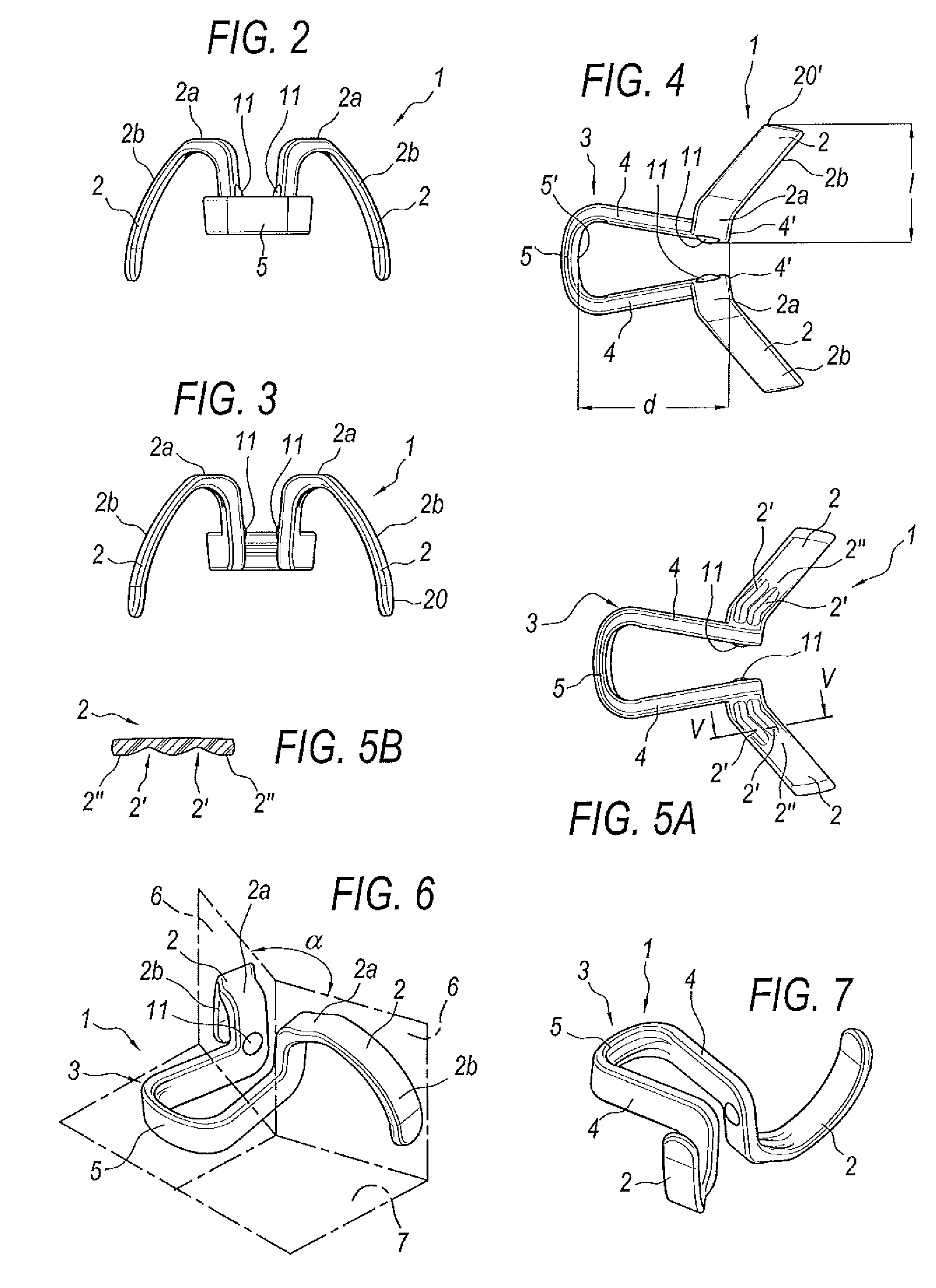
[0032]With reference to the accompanying drawings, in FIG. 1, the numeral 1 denotes in its entirety a mechanical anatomical dilator, which can be inserted in the nasal cavities, through the nostrils, to widen their transit cross-section and aid air flow, consequently making it easier for the user wearing the dilator 1 to breathe through his nose.

[0033]Therefore, this mechanical dilator can be inserted in the nasal cavities through the user's nostrils to aid air flow, and comprises a fork-shaped element 3 with a transversal bridge 5 designed, during use, to engage with the front face of the nasal septum, and from which there extend longitudinally corresponding arms 4 which can be inserted in the corresponding nasal cavities, from the free ends of the arms there extending laterally, cantilever-style, or in opposite lateral directions, respective elastic elements 2, having a general arched shape and designed to engage with and widen a corresponding zone of the nasal cavity. The elastic...


PUM


Abstract

A mechanical dilator (1), which can be inserted in the nasal cavities through the nostrils to aid air flow, includes two elastic elements (2), having an elongate arched shape, and a fork (3), having arms (4) which are connected by a bridge (5), the arms supporting the elastic elements (2), cantilever-style, on two sides of the fork (3), extending outwards from the arms.

Description

TECHNICAL FIELD[0001]This invention relates to a nasal dilator for increasing the patency of the nasal cavities and making it easier to breathe through the nose.[0002]It is known that sleep apnea and snoring are sometimes caused by a narrowing and at times occlusion of the nasal cavities.BACKGROUND ART[0003]To make breathing easier, above all while resting at night, there are prior art dilator devices which, when applied to the outside of the nose, help to widen the nasal cavities and allow increased air flow during breathing.[0004]Such dilators—due to their physical structure and the fact that they are located outside the nose during use—can be positioned by the user without a precise and exactly repeatable reference.[0005]Therefore, the resulting positioning has a certain degree of empiricism which does not allow the best use to be made of it relative to the precise anatomical shape and to the actual dimensions of the nose of each potential user. This condition is often also aggra...

Claims


Application Information

Patent Timeline
IPC IPC(8): A61M29/00
CPCA61F5/08
Inventor TASCA, IGNAZIO
Owner ILARIO MISTRO
Why Eureka
Try Eureka