
Articulator

a technology of articulator and articulator body, which is applied in the field of articulator, can solve the problems of a large number of errors, inability to disclose the proper method, and inability to measure the motion of the upper and lower jaw, and achieve the effect of simplifying the construction of such articulators, reducing the error range of articulators, and accurate articulation

Inactive Publication Date: 2012-12-27
LEE CHAE BUNG +1
View PDF5 Cites 3 Cited by
  • Summary
  • Abstract
  • Description
  • Claims
  • Application Information

AI Technical Summary

Benefits of technology

[0012]The present invention makes it possible to minimize the error ranges of the articulator by defining as a reference axis the point which is the center of the biological articulation of teeth, which results in an accurate articulation, and the construction of such articulator is simplified, and the manufacture of it is easy, and the manufacture cost is low.
[0013]In addition, since the position of the articulating plane surface can be set using the jig, the error range of the articulating can be more reduced.

Problems solved by technology

When considering only the position of the condylar as a reference axis, since the motions of the muscles are eliminated from considerations, errors inevitably occur when measuring the motions of upper and lower jaws.
In addition, there might be provided various adjusting means at the articulator for the purpose of adjusting error ranges in small ranges; however in case of the non-adjustable articulator, it is possible to measure only a simple opening and closing articulation because there is not provided a means for adjusting errors, so a proper method is not disclosed for correcting the errors.
The errors occur a lot when measuring the articulation, so a post-process is inevitably needed in a state that a patient has a prosthetic appliance.
A lot of difficulties are needed when mounting accurately them using the above mentioned means, and minor errors occur owing to the thickness of the auxiliary means.

Method used


Image

  • Articulator
  • Articulator
  • Articulator

Examples


Embodiment Construction

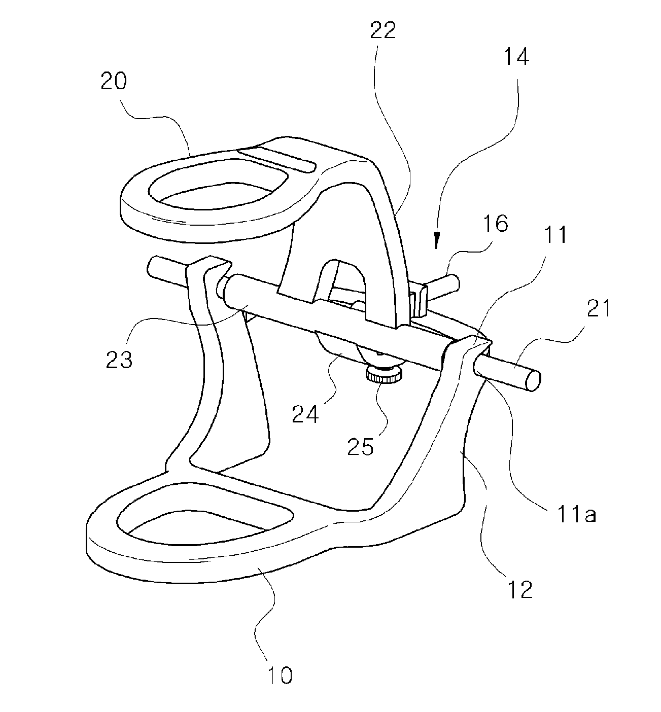
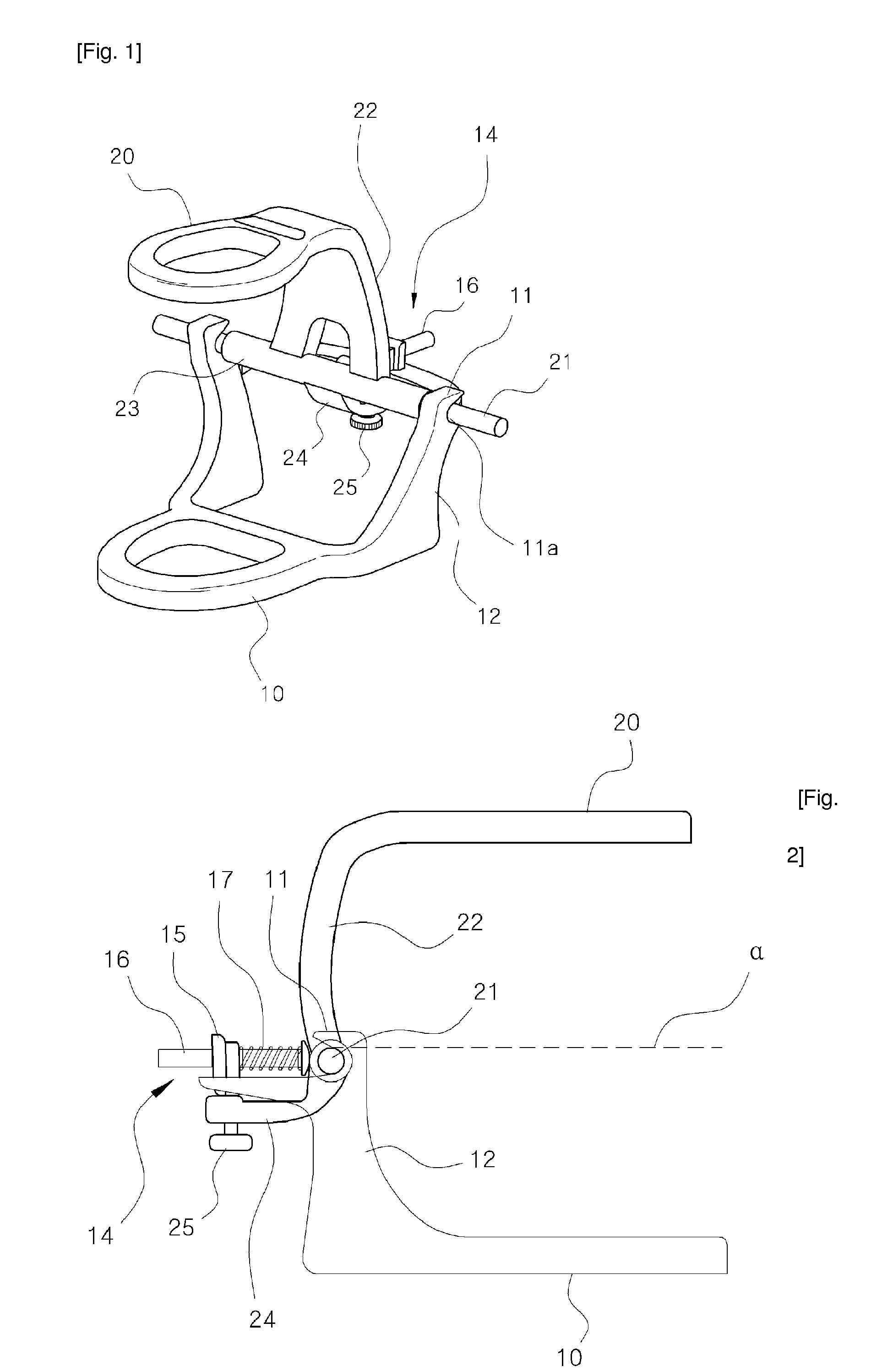
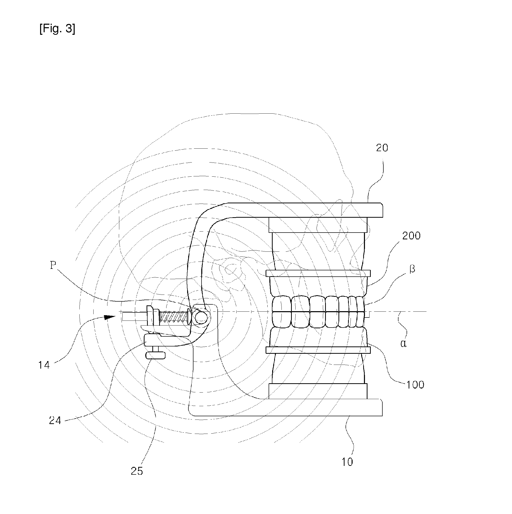
[0028]The articulator comprises a lower jaw mounting plate 10 configured to mount a lower jaw model 100; an upper jaw mounting plate 20 configured to mount an upper jaw model 200; and an engaging part 11 and a rotary shaft 21 which are formed at the lower jaw mounting plate 10 and the upper jaw mounting plate 20, respectively, and are axially engaged, and columns 12 and 22 formed at the rear sides of the lower jaw mounting plate 10 and the upper jaw mounting plate 20 have the same vertical heights, and as the rotary shaft 21 is positioned on an extended line of the articulating plane surface (α), so the lower jaw mounting plate 10 and the upper jaw mounting plate 20 are symmetrically positioned upward and downward about the rotary shaft 21, and when the upper jaw model 200 and the lower jaw mode 100 are folded upward and downward, the tangent line (β) of the rotational motion is vertically applied to the articulating plane surface.

MODES FOR CARRYING OUT THE INVENTION

[0029]Hereinafte...


PUM


Abstract

The present invention relates to an articulator used for the purpose of checking the alignment of dentures, by coupling together models of the upper and lower jaws, in order to provide a simple movement of the upper and lower jaws, minimize occlusal errors, and accurately mount the upper and lower jaws on the occlusion surface. Conventional articulators imitate the form of upper and lower jaw movements, wherein a reference axis is established and folded in accordance with a condyle, however, the process completely eliminates muscle movement, and inevitably leads to occlusal errors of the upper and lower jaw movement. Consequently, the problem with conventional articulators is the need for post-processing, regardless of the extent of reduction of the occlusal errors through the use of diverse assisting means. In addition, while accurate occlusion cannot be achieved, conventional articulators have a structure that is too complicated and difficult to operate. Therefore, in a non-arcon type articulator, a reference axis is formed on a line extending from the central plane of an upper jaw mounting plate and a lower jaw mounting plate, so that the tangent of rotation creates a vertical motion on the occlusion surface, which allows upward and downward movements that are closer to physiological movements than conventional assisting means, which require making fine adjustments to occlusion, minimizes the margin of error of the articulator, and provides a simple operating structure for the upper and the lower jaw mounting plates and an easier usage thereof.

Description

TECHNICAL FIELD[0001]The present invention relates to an articulator which makes it possible to check an arranging relationship of teeth in such a way to attach upper and lower law models, and particularly to an articulator which makes it possible to minimize an articulating error and to mount accurately an upper jaw and a lower jaw on an articulating surface while ensuring a simple motion structure of an upper jaw and a lower jaw.BACKGROUND ART[0002]An articulator is a device generally used for the sake of a manufacture and diagnosis of denture, tooth crown restoration, prosthetic appliance, etc. by measuring a coupled state of teeth and a gum and is configured to mechanically imitate and reproduce a relative position relationship of a jawbone and teeth with respect to a cranium and the motions of a lower jaw.[0003]The upper and lower jaw motions of a human being's body come as a lower jaw bone moves with an upper jaw bone not moving, so most of the articulators are designed imitat...

Claims


Application Information

Patent Timeline
IPC IPC(8): A61C11/00
CPCA61C11/06A61C11/02
Inventor LEE, CHAE BUNGKIM, SE HUN
Owner LEE CHAE BUNG
Learn More