
Systems for detecting a febrile condition and reducing risks of spreading infection

a technology for detecting febrile conditions and reducing the risk of spreading infection, which is applied in the field of scanning, can solve the problems of individuals resisting such procedures, difficult to carry out such monitoring, and not being able to find the infected individual

Active Publication Date: 2012-12-20
HELLER ALAN CAMERIK
View PDF9 Cites 31 Cited by
  • Summary
  • Abstract
  • Description
  • Claims
  • Application Information

AI Technical Summary

Benefits of technology

[0010]Optionally, the receiver may be part of a hand-held device that includes a second transmitter. The second transmitter transmits received temperature and identifying data by WiFi, WiMax...

Problems solved by technology

However, there does not appear to be a ready solution to the issue of identification of the infected individual.
Measuring core body temperature, unlike measurement of body surface temperature, poses several challenges, however.
Accordingly, it is challenging to carry out such monitoring on a periodic basis for large groups of people.
Indeed, it is quite likely that individuals may resist such procedures.
But, merely measuring a surface body temperature is not generally as reliable an indicator of infection because it is influenced by external conditions, such as ambient temperature, clothing, etc.
The core body temperature, poses challenges as well because core body temperature varies from one individual to another as an inherent condition of the individual.

Method used


Image

  • Systems for detecting a febrile condition and reducing risks of spreading infection
  • Systems for detecting a febrile condition and reducing risks of spreading infection
  • Systems for detecting a febrile condition and reducing risks of spreading infection

Examples


Embodiment Construction

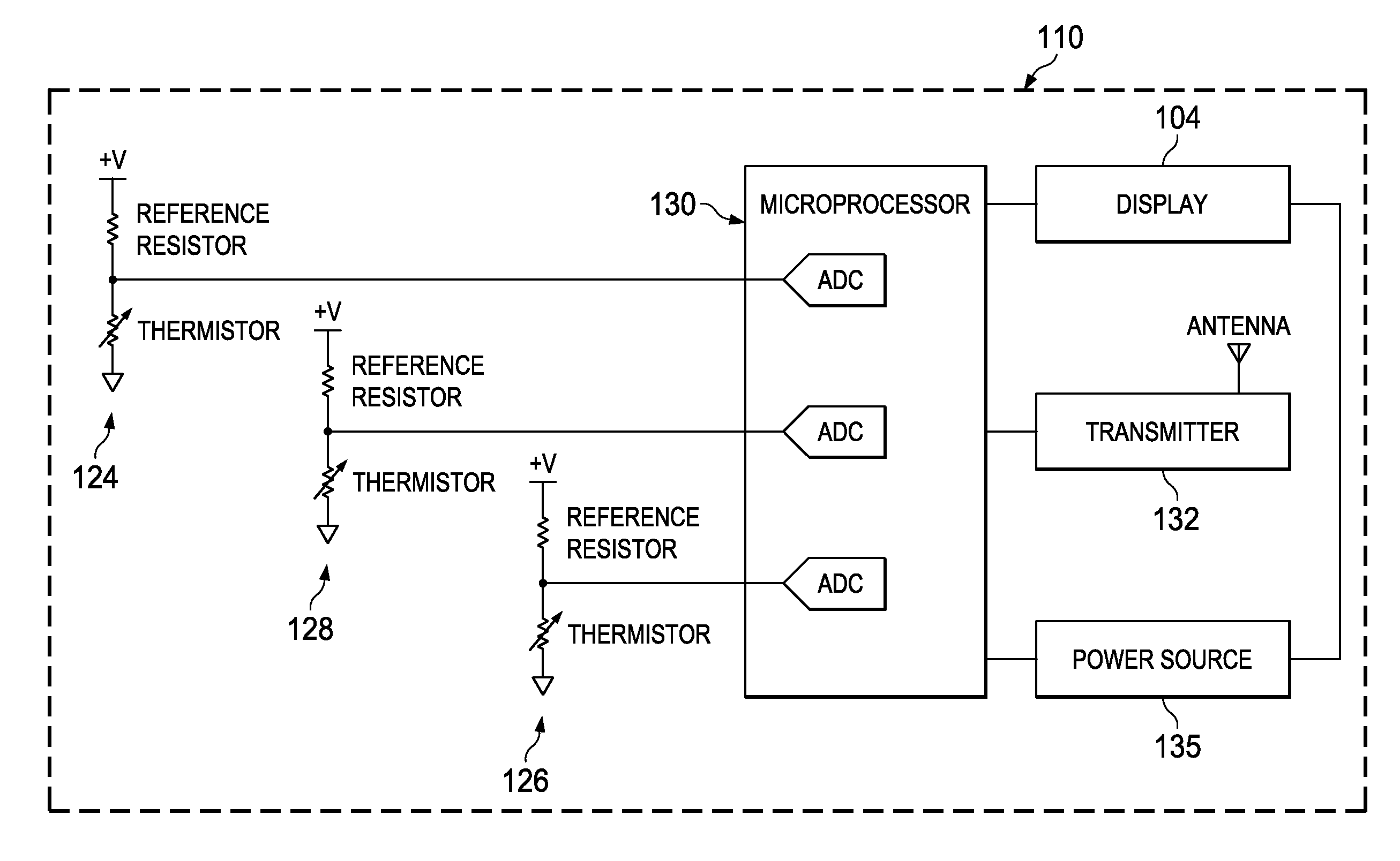
[0020]The following detailed description provides a description of exemplary embodiments of the technology claimed here below to facilitate an understanding of the technology, but does not limit the scope of the technology claimed.

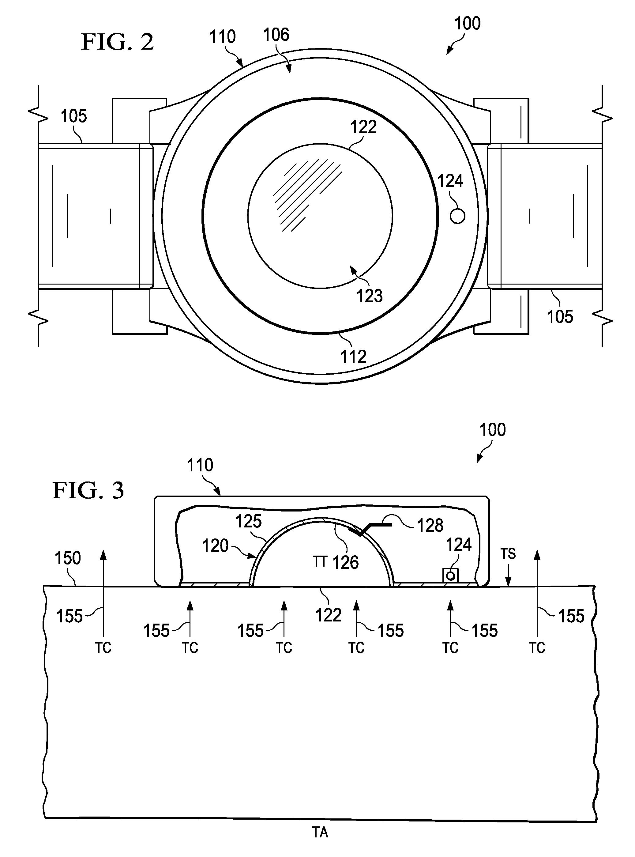
[0021]The term “exemplary” as applied to embodiments means “an example of.” The term “heat trap” means a structure that is designed to receive incoming thermal energy, trap that thermal energy and minimize losses of thermal energy from its structure. An exemplary embodiment described herein has a shell of a material that is resistant to thermal energy passing through it (i.e. it is a “thermally insulative” material, or a “low thermal conductivity” material) with an inner thermally reflective surface that may include a coating or lining of a heat reflective material.

[0022]As a preliminary matter, there are several factors that may, or ought, to be taken into account in making a determination about whether an individual is exhibiting a febrile condition. A k...


PUM


Abstract

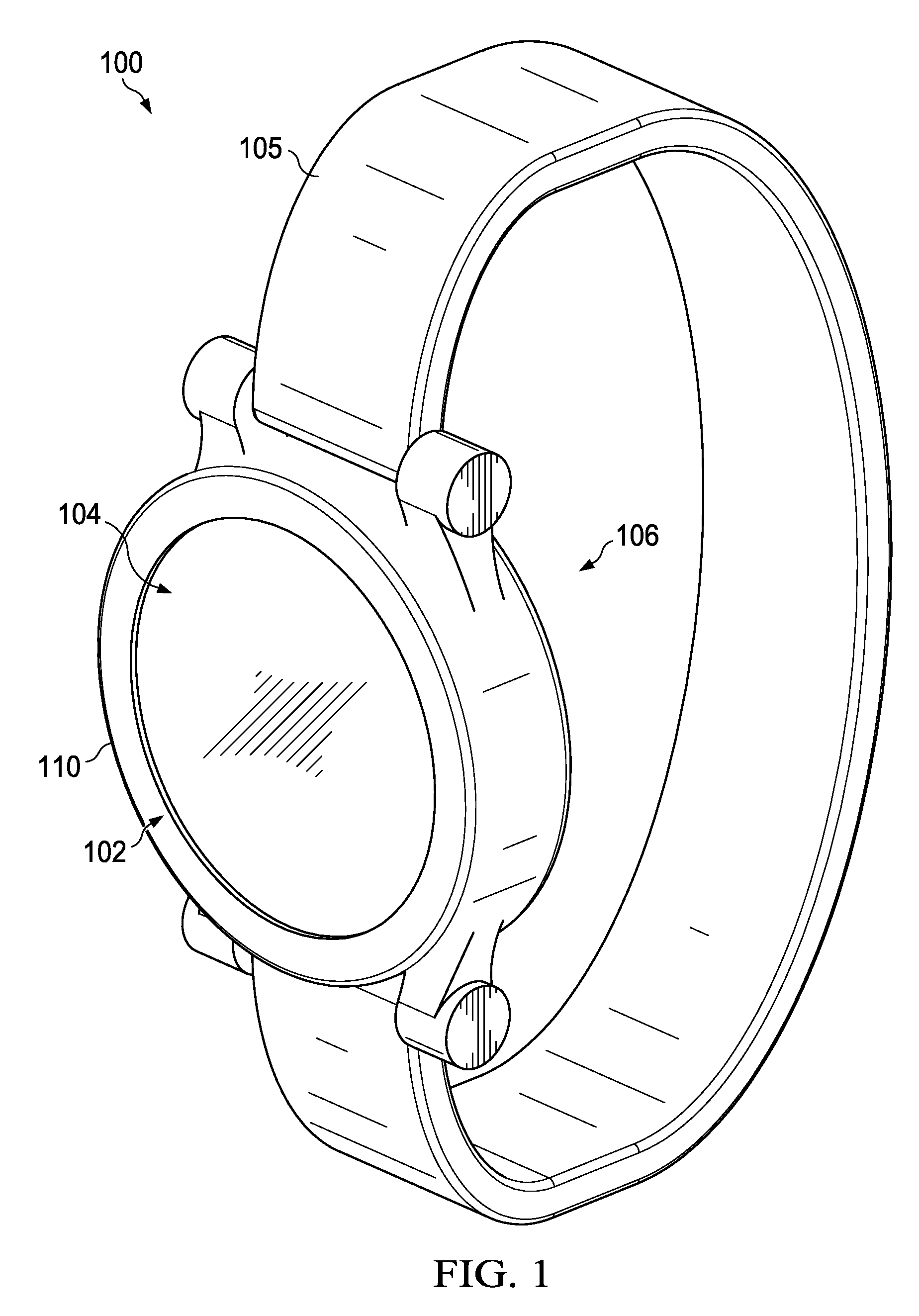
The technology provides an external device for estimating a core body temperature of a human subject, and a system for use in a local area, such as a school, hospital, workplace, and the like. The wrist monitor device includes a casing sized and shaped to fit onto a wrist of a human subject. The casing has a first face and a second face. In addition there is a cavity in the casing that houses a heat trap. The heat trap has an opening oriented to receive incoming thermal energy and a shell of a thermal-insulation material that has an inner thermal energy-reflective surface. Detected temperature data is compiled in a database and used to estimate whether an identified individual has a core body temperature indicative of a fever. There is also provided a system for identifying persons and screening the persons for a febrile condition. The system may include the steps of: identifying a person using data input by the individual or detected from indicia of the person and previously stored data about the person; detecting a temperature condition of the person; determining whether the person has a febrile condition using the detected temperature condition and previously stored temperature data of the person; and taking action to restrict ingress, deny ingress or allow ingress, based on the determined febrile condition of the person requiring ingress.

Description

BACKGROUND[0001]1. Field of the Invention[0002]The technology relates to systems for scanning to determine a febrile condition in a human subject as a preliminary parameter to allow or deny ingress to a protected facility, and more particularly, it relates to a system for accumulating and processing temperature data to identify individuals exhibiting a temperature condition indicating an actual or potential health condition.[0003]2. Description of the Related Art[0004]It has been become increasingly necessary to detect and identify people that may be infected with a contagious illness, whether bacterial or viral. People are very mobile, traveling from city to city and country to country, and that factor makes it even more important to identify infected persons, to prevent or at least minimize the potential for the spread of disease. In recent years there has been mounting concern about such international infectious diseases as SARS in recent years, and concerns about infections tran...

Claims


Application Information

Patent Timeline
IPC IPC(8): G08B23/00A61B6/00A61B5/01
CPCA61B5/0008A61B5/01A61B5/681G01K13/002A61B2562/0271G01K7/22A61B2560/0214A61B5/742A61B5/7225A61B5/0022G01K1/165G01K13/20
Inventor HELLER, ALAN CAMERIK
Owner HELLER ALAN CAMERIK
Learn More