
Reducing waste in metal stamping processes and systems therefor

a technology of metal stamping and waste, which is applied in the field of devices and methods for reducing waste in metal stamping lines, can solve the problems of increasing the cost of materials in the metal industry, such as flat rolled steel, and achieve the effect of reducing the cost of materials

Active Publication Date: 2012-12-20
HONDA MOTOR CO LTD
View PDF6 Cites 13 Cited by
  • Summary
  • Abstract
  • Description
  • Claims
  • Application Information

AI Technical Summary

Benefits of technology

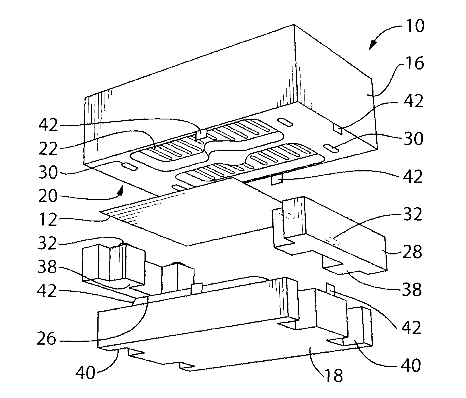
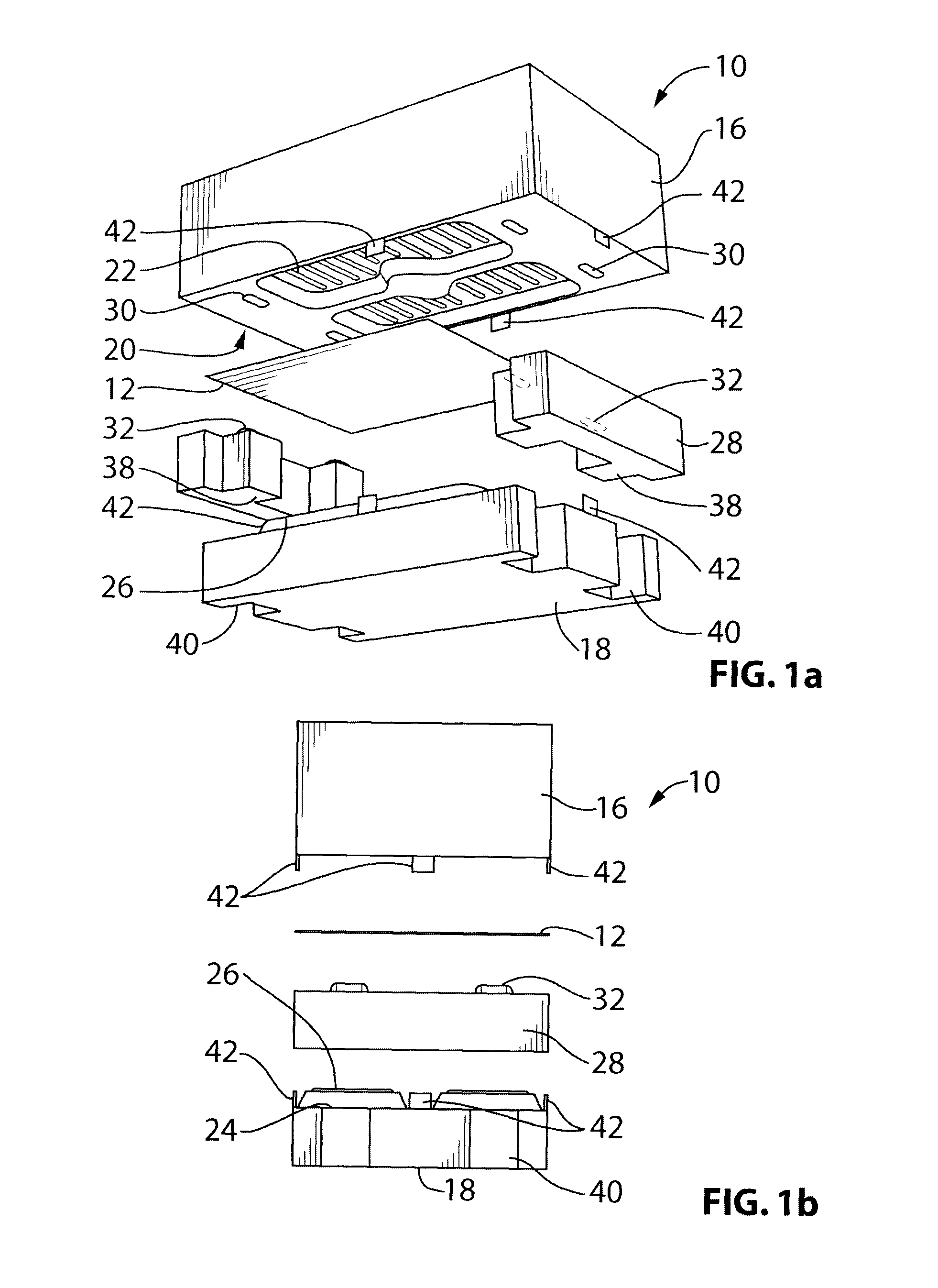
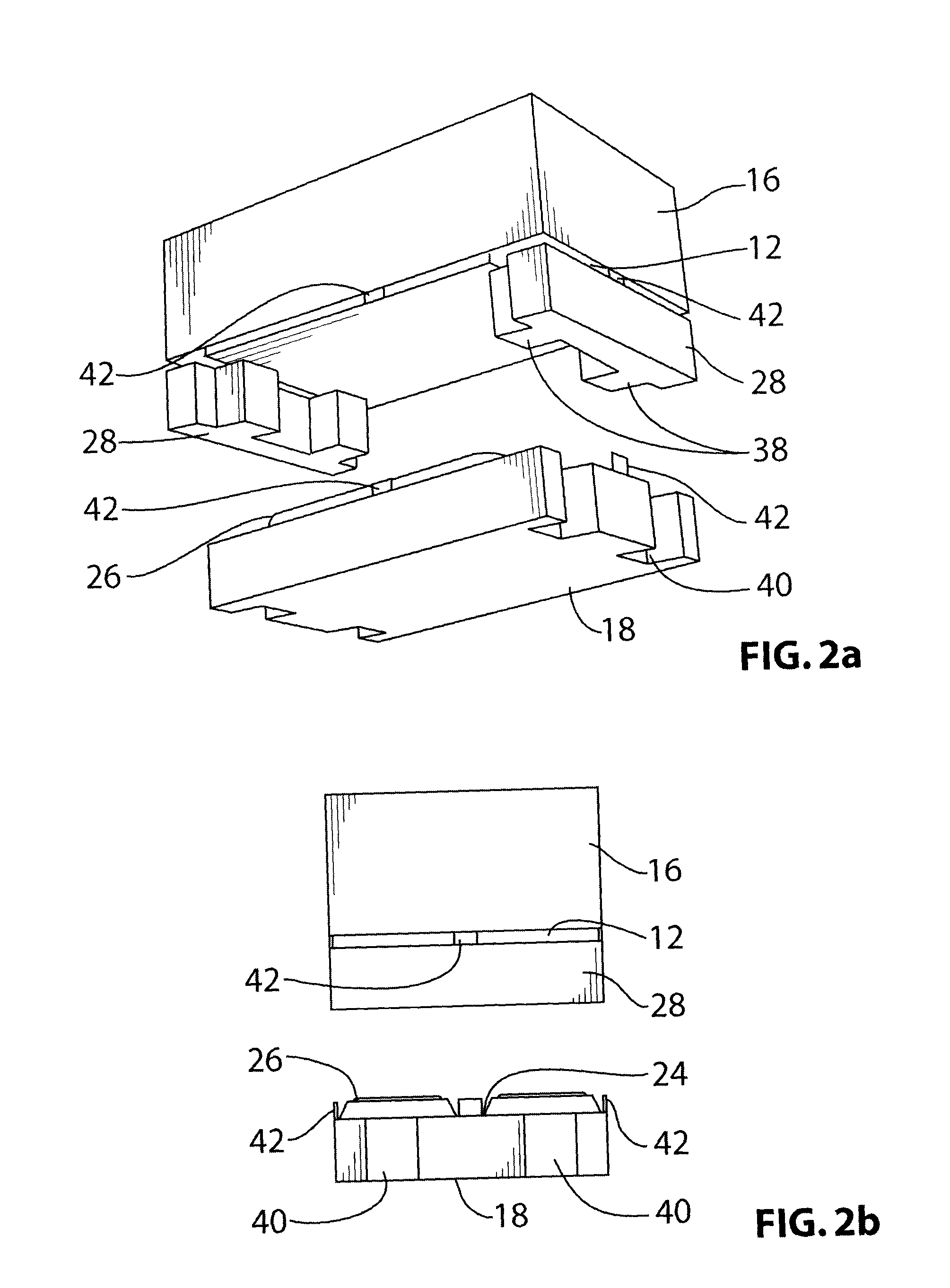
[0012]In some exemplary embodiments, the intermediate clamp section further comprises a blank shifting member operable for aligning the blank for clamping with first and second clamping formations and / or the third and fourth clamping formations. In various exemplary embodiments, the blank shifting member is an actuated member suitable for aligning and maintaining the blank in a desired clamping position. Furthermore, in various exemplary embodiments, the actuated member is a hydraulic cylinder with a piston carrying an effector operatively coupled to the intermediate clamp section such that the piston may align and maintain the blank in the desired clamping position.
[0013]In another exemplary embodiment, there is provided a method for reducing the required length of a blank to produce a stamped part therefrom. The method comprises the steps of:

Problems solved by technology

The cost of materials in the metal industry, such as flat rolled steel, has been increasing, rapidly given the world supply and demand as well as increasing energy costs required to produce various metal products.

Method used


Image

  • Reducing waste in metal stamping processes and systems therefor
  • Reducing waste in metal stamping processes and systems therefor
  • Reducing waste in metal stamping processes and systems therefor

Examples


Embodiment Construction

[0058]It should be understood that the present disclosure is not limited in its application to the details of construction and the arrangement of components set forth in the following description or illustrated in the drawings. The invention is capable of other embodiments and of being practiced or of being carried out in various ways. Also, it is to be understood that the phraseology and terminology used herein is for the purpose of description and should not be regarded as limiting. The use of “including,”“comprising,” or “having” and variations thereof herein is meant to encompass the items listed thereafter and equivalents thereof as well as additional items. Unless limited otherwise, the terms “connected,”“coupled,” and “mounted,” and variations thereof herein are used broadly and encompass direct and indirect connections, couplings, and mountings. In addition, the terms “connected” and “coupled” and variations thereof are not restricted to physical or mechanical connections or...


PUM

PropertyMeasurementUnit
sizesaaaaaaaaaa
lengthaaaaaaaaaa
perimeteraaaaaaaaaa

Abstract

Disclosed herein is a sheet metal stamping device and methods for reducing the size of a blank required for producing a stamped part therefrom than is conventionally possible. The device utilizes an intermediate clamp section with projections having clamping formations located thereon which complement clamping formations located on a first die section. The intermediate clamp section projections allow for the use of a smaller blank size as less addendum material is required to secure the blank during the stamping process. The blank is secured using the intermediate clamp section and the first die section prior to the second die section engaging the blank to stamp the part. In some embodiments, retention beads resultant from the clamping process may remain in the stamped part, that being inside a trim line. Furthermore, in some embodiments, a blank shifter may be provided to locate the blank between the die sections prior to clamping. In other embodiments, more than one complementary pair of clamping formations may be provided. Furthermore, in some embodiments a trim line cutter may be provided.

Description

FIELD[0001]The present disclosure relates to devices and methods for reducing waste in metal stamping lines.BACKGROUND[0002]The cost of materials in the metal industry, such as flat rolled steel, has been increasing, rapidly given the world supply and demand as well as increasing energy costs required to produce various metal products. Between 2003 and 2009 the average steel price has increased by about three times and is projected to increase about an additional 15% by 2011; far exceeding the anticipated rate of inflation.[0003]When sheet metal blanks are used to produce stamped metal parts, excess material is required about the perimeter of the blank. This excess material is known as the addendum and is used as a region for clamping and maintaining the blank in place during the stamping process. Ultimately the addendum is removed from the final part and scrapped.[0004]Since the addendum is not integral to the final part resulting from the stamping process and is ultimately removed...

Claims


Application Information

Patent Timeline
Patent Type & Authority Applications(United States)
IPC IPC(8): B21D22/06B21D28/14
CPCB21D22/06B21D24/04B21D22/22
Inventor MOORE, WILLIAM R.GLENN, KEVIN P.
Owner HONDA MOTOR CO LTD
Learn More