
Separator for articles of laundry

Active Publication Date: 2012-12-06
MCCABE STANLEY G
View PDF17 Cites 7 Cited by
  • Summary
  • Abstract
  • Description
  • Claims
  • Application Information

AI Technical Summary

Benefits of technology

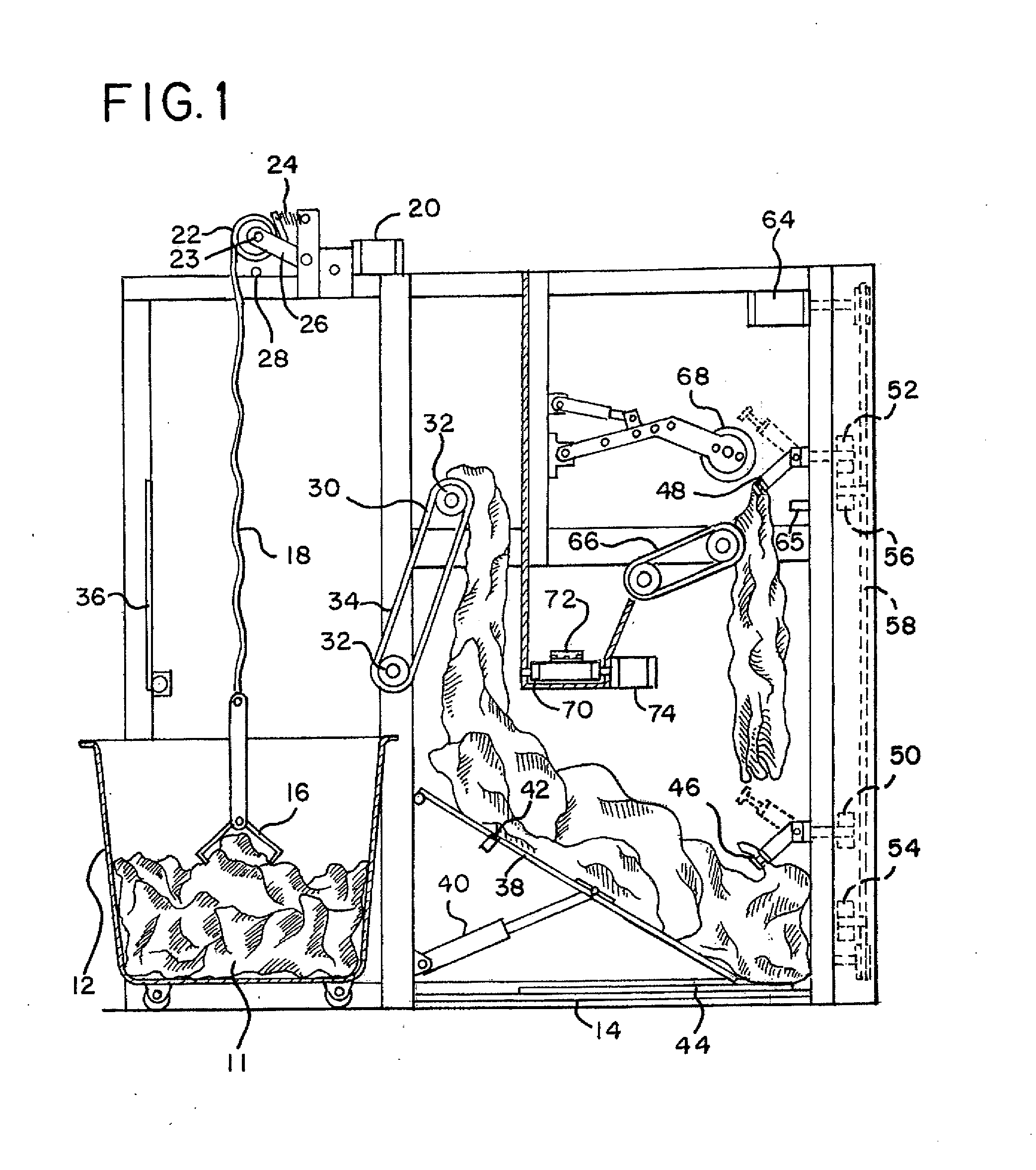
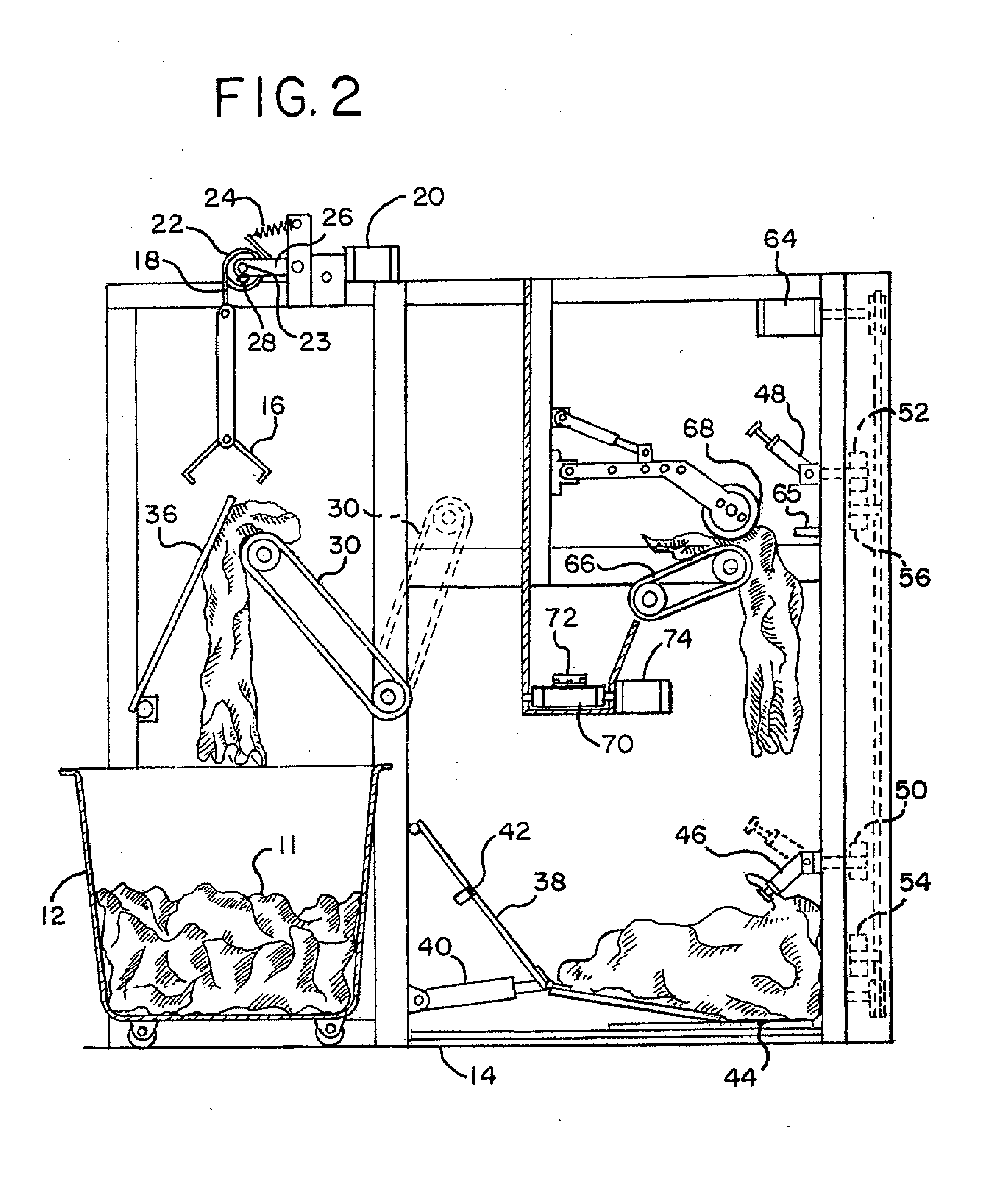
[0005]In a first stage, a strap is used to raise and lower a clamp. Slack in the strap is used to determine when the clamp reaches the bundle for clamping and triggering raising of the clamp. In a second stage, a non-horizontal conveyor tilts beneath the clamp to receive multiple articles, and then tilts over another bin to deposit the articles while conveying towards the other bin. In a third stage, the second bin includes a hinged or angled surface. The surface is straightened to shift the articles towards a clamp and relaxed or bent to keep too many articles from piling up at the clamp. In a fourth stage, the clamp or clamps are supported by, but not attached to, a support connected with the drive. When the clamp or clamps reach the pile of articles, the clamp or clamps stop but the support may continue to move, allowing easier drive control. In a fifth stage, the clamp is tiltable in two directions, such as downward and upward. By titling away from a direction of travel when passing an article, the clamp is less likely to get caught or damage the article. In a sixth stage, the article is transferred by an air jet onto a surface with a roller separated from the surface. Upon transfer, the roller forms a nip with the surface with the article in the nip. In a seventh stage, the article is deposited on an exit conveyor. The exit conveyor has a flexible, raised portion to push and / or drag the article at a rapid speed to the exit.

Problems solved by technology

Since sheets have large dimensions with thin fabric, the sheets are often tangled together, necessitating either an automated separator machine or an operator for manually locating the edges or corners.
Where possible, automated processes may save money over time.
Such devices operate too slowly or have maintenance problems, such as due to rapid, yanking oscillation of components.

Method used


Image

  • Separator for articles of laundry
  • Separator for articles of laundry
  • Separator for articles of laundry

Examples


Embodiment Construction

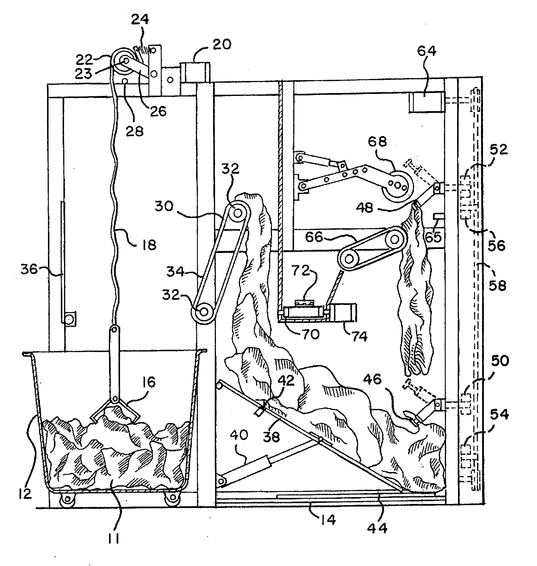
[0022]FIGS. 1-5 show various aspects of one embodiment of a separator. Various stages and aspects of the embodiment may be altered or changed based on now known or later developed devices or methods. The separator isolates the articles of laundry from a load or bundle of articles. Various stages or aspects may be used in other types of devices, such as spreaders, ironers or folders. For example, the strap for raising and lowering the clamp or the tiltable clamp stages may be used in a spreader.

[0023]The separator described herein is adapted for separating rectangular or square sheets. For example, flannel or cotton sheets in single, double, queen and / or king sizes are processed. A given bundle may include only articles of the same type and size, but may include a mix of types and / or sizes. Larger or smaller articles of laundry may also be processed, such as blankets, comforters, towels, pillow cases, pillow shams, or other laundry articles. The articles are wet, damp, or dry. For ex...


PUM


Abstract

A separator separates sheets from a bundle. Slack in the strap used to raise and lower a clamp is used to determine when the clamp reaches the bundle. A non-horizontal conveyor tilts beneath the clamp to receive multiple articles, and then tilts over another bin to deposit the articles. The second bin includes an angled surface, which is straightened to shift the articles for clamping. The clamp is supported by, but not attached to, a support connected with the drive. When the clamp reaches the pile, the clamp stops but the support may continue to move. The clamp is tillable. The article is transferred by an air jet onto a surface with a roller separated from the surface. Upon transfer, the roller forms a nip with the surface. The article is deposited on an exit conveyor having a flexible, raised portion.

Description

BACKGROUND[0001]The present invention relates to automated laundry separators or other laundry processing devices.[0002]Many processes in laundries are automated. For example, machines in hotels spread out, iron, and fold sheets without operator intervention. To begin the automated process, the operator identifies either corners or an edge of the sheet and places the corners or edge into a spreader machine. Since sheets have large dimensions with thin fabric, the sheets are often tangled together, necessitating either an automated separator machine or an operator for manually locating the edges or corners.[0003]A separator receives a jumble or bundle of articles, such as a compressed cake of linen or cartor cart (e.g., truck) of sheets from a washer or dryer. The separator separates individual articles from the bundle and outputs individual pieces or a few pieces together for easier feeding into the next stage of automated processing. Where possible, automated processes may save mon...

Claims


Application Information

Patent Timeline
IPC IPC(8): D06F95/00B65G49/00B25J15/00B65G65/02
CPCD06F67/04B66C1/58D06F95/00
Inventor MCCABE, STANLEY G.
Owner MCCABE STANLEY G
Learn More