Solar battery cell, solar battery module and method of making solar battery module

Active Publication Date: 2012-12-06
RESONAC CORP
View PDF5 Cites 13 Cited by
  • Summary
  • Abstract
  • Description
  • Claims
  • Application Information

AI Technical Summary

Benefits of technology

[0013]In the solar battery cell according to the present invention, the exposed portion is formed on the back surface in such a manner that the substrate is exposed from the exposed portion in association with the position on the light receiving surface where the TAB wire is to be connected, and the exposed portion corresponds to the alignment mark indicative of the position on the back surface where the TAB wire is to be connected. Thus, the TAB wire can be accurately connected to an intended position. Furthermore, the alignment mark can be easily formed by avoiding applying an electrode material to a portion of the back surface which corresponds to the alignment mark when the back surface electrode is formed. Hence, a possible increase in manufacturing costs can be suppressed.
[0023]The present invention can provide a solar battery cell and related methodology which enable the TAB wire to be accurately connected to the intended position, while allowing a possible increase in manufacturing costs to be suppressed.

Problems solved by technology

Thus, the yield of the connection step may decrease or the solar battery cells may be warped.
However, in this case, manufacturing costs increase.
However, Ag is expensive, thus contributing to increasing costs.
This increases power loss, thereby reducing the power generation performance of the solar battery cells.
This further increases the manufacturing costs.
This suppresses a decrease in the yield of the connection step and the warpage of the solar battery cells.
Furthermore, if the conductive adhesive is used to connect the TAB wire, the wettability need not be ensured.
However, avoidance of formation of bus bar electrodes on the front or back surface of the solar battery cell prevents identification of the position where the TAB wires are connected.
This may preclude the TAB wires from being accurately stuck to intended positions.
When the TAB wires fail to be stuck to the intended positions, the lines of the solar battery cells may meander.
Then, a residual stress may be generated in the solar battery cells, and the manufacturing yield may decrease.
However, a complicated step of forming alignment marks increases the manufacturing costs.

Method used


Image

  • Solar battery cell, solar battery module and method of making solar battery module
  • Solar battery cell, solar battery module and method of making solar battery module
  • Solar battery cell, solar battery module and method of making solar battery module

Examples


first embodiment

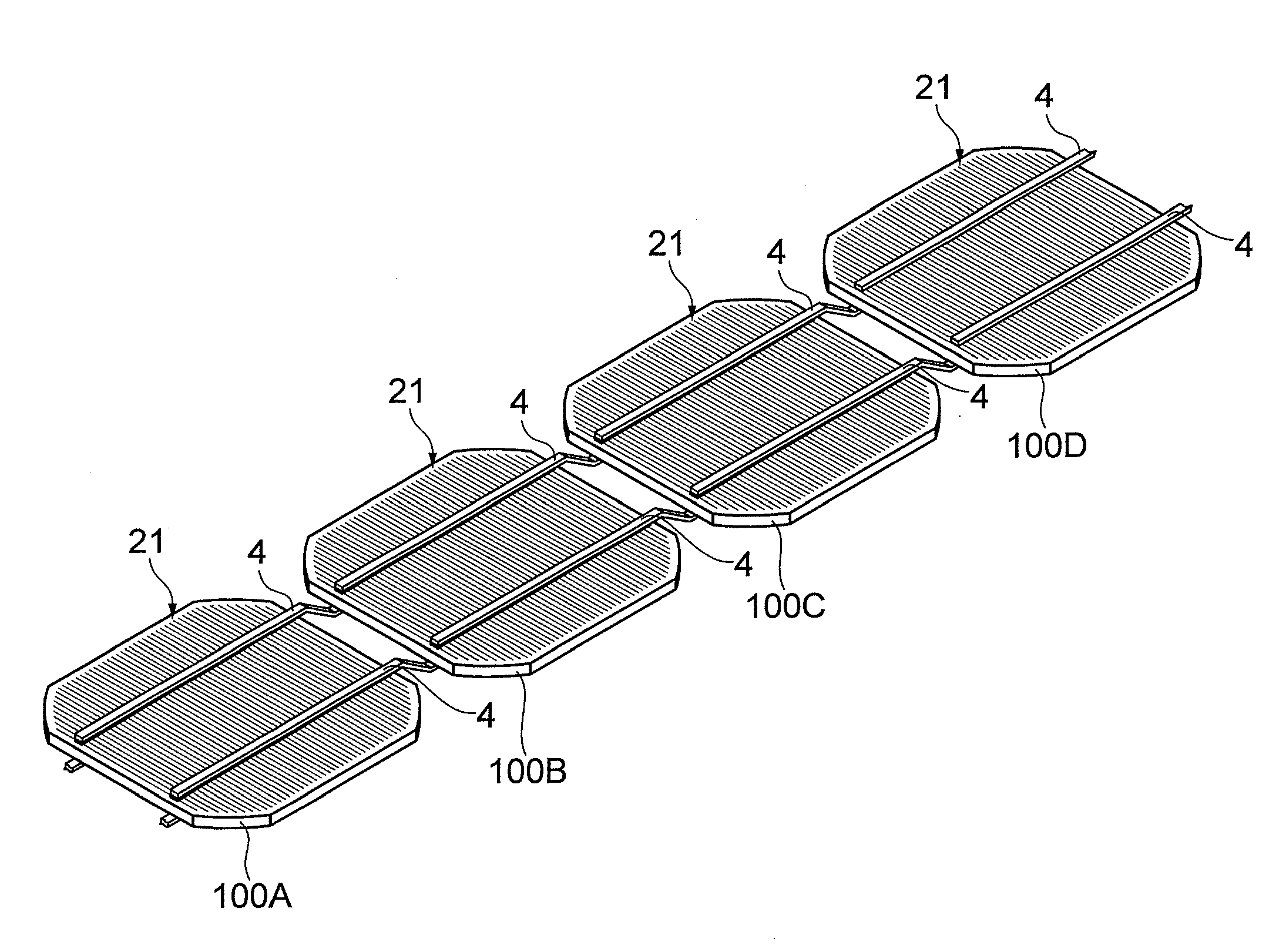
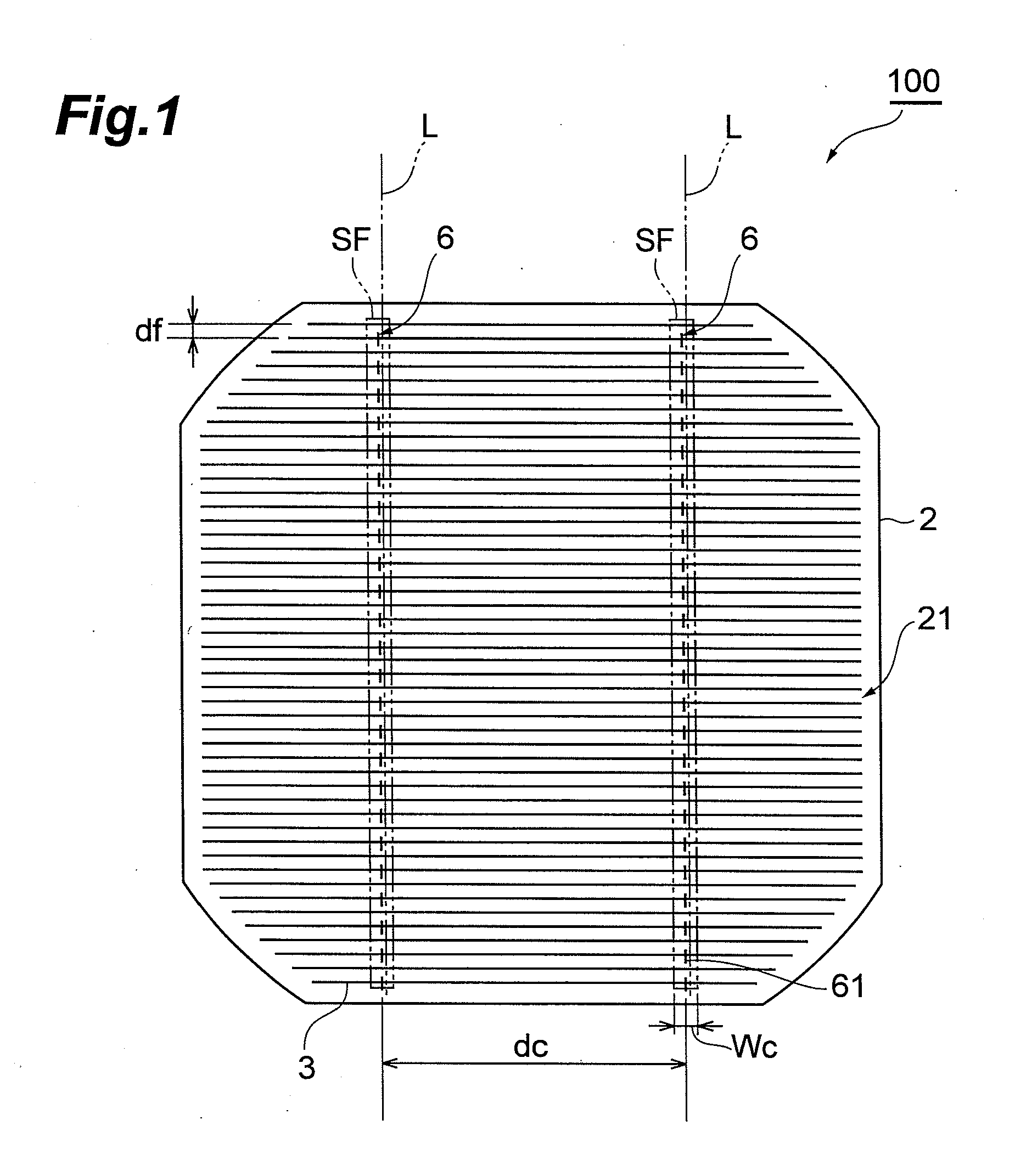
[0039]FIG. 1 is a plan view showing a light receiving surface of a solar battery cell according to the present invention. FIG. 2 is a bottom view showing a back surface of the solar battery cell in FIG. 1. FIG. 3 is a perspective view showing that a plurality of the solar battery cells in FIG. 1 are connected together. FIG. 4 is a schematic side view of FIG. 3.

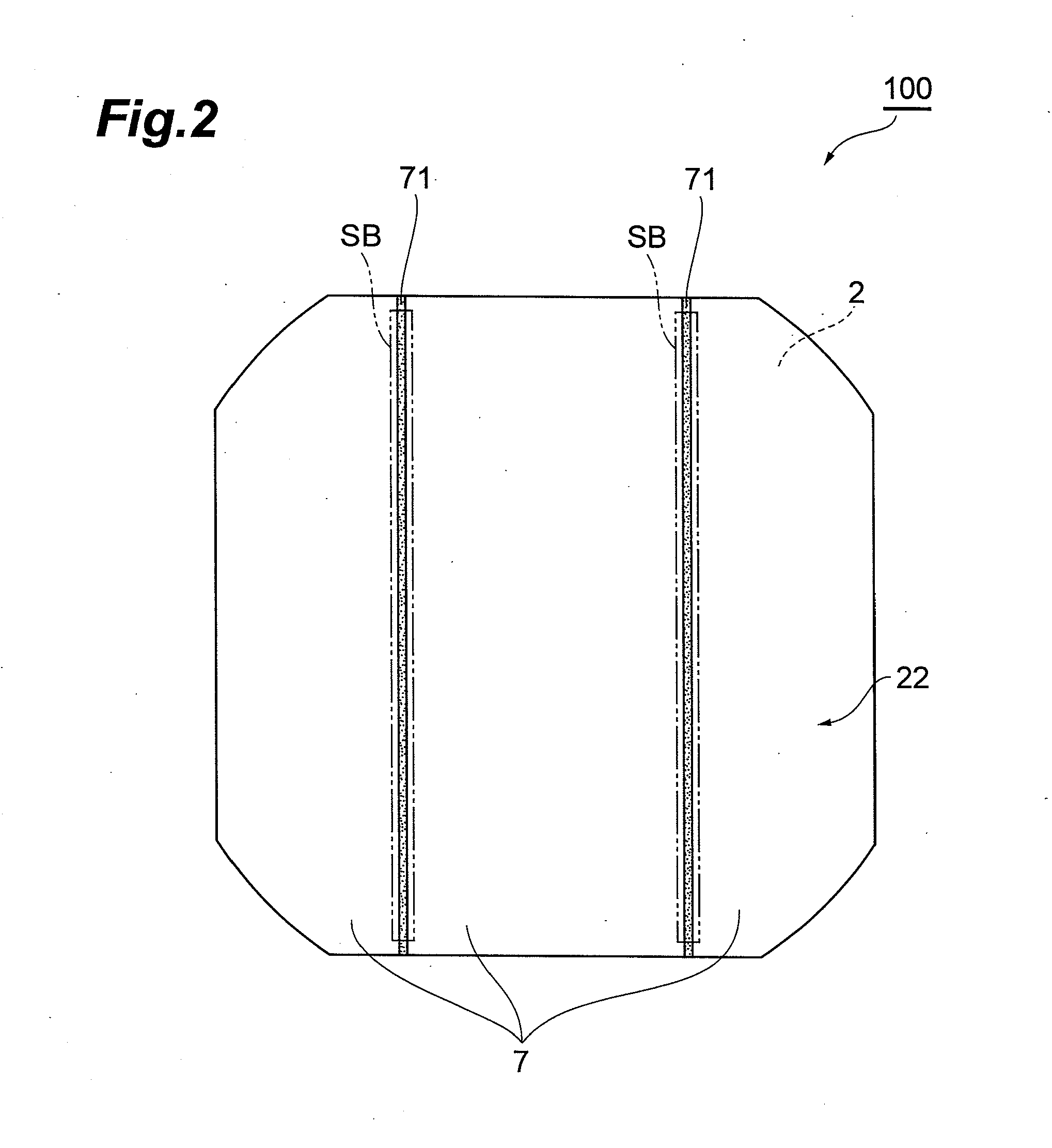
[0040]As shown in FIG. 1, a solar battery cell 100 is such that a plurality of the solar battery cells 100 are electrically connected together in series or parallel to form one solar battery module. The solar battery cell 100 includes a substrate 2. The substrate 2 is generally square and has four circular-arc corners. One surface of the substrate 2 corresponds to a light receiving surface 21. The other surface of the substrate 2 corresponds to a back surface 22 (see FIG. 2). The substrate 2 may be formed of at least one of a single crystal of Si, a polycrystal of Si, and a non-crystal of Si. On the light receiving surface 21 ...

third embodiment

[0070]Of course, the solar battery cell 400 described above exerts effects similar to those of the solar battery cell 300 according to the

[0071]Now, a solar battery cell according to a fifth embodiment of the present invention will be described. In the present embodiment, mainly differences from the above-described third embodiment will be described.

[0072]FIG. 8 is a plan view showing a back surface of the solar battery cell according to the fifth embodiment of the present invention. As shown in FIG. 8, a solar battery cell 500 according to the fifth embodiment is different from the solar battery cell 300 according to the third embodiment (see FIG. 6) in that the solar battery cell 500 includes back surface alignment marks 75 each with the thick line portions 73b longer than the thin line portions 73a, instead of the back surface alignment marks 73 each with the thin line portions 73a and the thick line portions 73b similar in length.

[0073]Of course, the solar battery cell 500 descr...


PUM


Abstract

A solar battery cell and related methodology are provided which enable a TAB wire to be accurately connected to an intended position, thus allowing a possible increase in manufacturing costs to be suppressed. The solar battery cell can include a substrate, a plurality of finger electrodes formed on a light receiving surface of the substrate, and a back surface electrode on a back surface of the substrate, the back surface electrode to be connected to a plurality of finger electrodes on an adjacent cell by applying a first TAB wire via a conductive adhesive, wherein the back surface electrode has omitted portions arranged to define at least one alignment marking indicative of a position where the first TAB wire is to be applied, the at least one alignment marking having a width less than a width of said first TAB wire.

Description

BACKGROUND OF THE INVENTION[0001]1. Field of the Invention[0002]The present invention relates to a solar battery cell, a solar battery module and a method of making solar battery module.[0003]2. Related Background Art[0004]In recent years, much attention has been paid to solar batteries as means for solving increasingly serious global warming and fossil energy depletion problems. A solar battery is normally formed by connecting a plurality of solar battery cells together in series or parallel. The solar battery cell includes a plurality of linear electrodes (finger electrodes) arranged in parallel on a front surface (light receiving surface) thereof and formed of Ag in order to provide power. A back surface electrode formed of Al is formed all over a back surface of the solar battery cell. Then, adjacent solar battery cells are connected together by connecting a metal wiring member (TAB wire) to the light receiving surface of one of the adjacent solar battery cells so that the metal...

Claims


Application Information

Patent Timeline
IPC IPC(8): H01L31/05H01L31/18H01L31/0224
CPCY02E10/50H01L31/0512H01L31/0504H01L31/022433
Inventor TSURUOKA, YASUOTAKEMURA, KENZOUASAKAWA, YUSUKEFUJII, MASAKI
Owner RESONAC CORP
Why Eureka
Try Eureka