Solar battery cell, solar battery module, method of making solar battery cell and method of making solar battery module

a solar battery and module technology, applied in the field of solar battery modules, can solve the problems of increasing manufacturing costs, warping of solar battery cells, and reducing the yield of connection steps, and achieve the effect of suppressing the increase in manufacturing costs

Inactive Publication Date: 2012-09-13
HITACHI CHEM CO LTD
View PDF8 Cites 7 Cited by
  • Summary
  • Abstract
  • Description
  • Claims
  • Application Information

AI Technical Summary

Benefits of technology

[0019]The present invention can provide a solar battery cell and related methodology that enable the TAB wire to be accurately connected to intended position, while allowing a possible increase in manufacturing costs to be suppressed.

Problems solved by technology

Thus, the yield of the connection step may decrease or the solar battery cells may be warped.
However, in this case, manufacturing costs increase.
However, Ag is expensive, thus contributing to increasing costs.
This increases power loss, thereby reducing the power generation performance of the solar battery cells.
This further increases the manufacturing costs.
This suppresses a decrease in the yield of the connection step and the warpage of the solar battery cells.
Furthermore, if the conductive adhesive is used to connect the TAB wire, the wettability need not be ensured.
However, avoidance of formation of bus bar electrodes on the front or back surface of the solar battery cell prevents identification of the position where the TAB wires are connected.
This may preclude the TAB wires from being accurately stuck to intended positions.
When the TAB wires fail to be stuck to the intended positions, the lines of the solar battery cells may meander.
Then, a residual stress may be generated in the solar battery cells, and the manufacturing yield may decrease.

Method used


Image

  • Solar battery cell, solar battery module, method of making solar battery cell and method of making solar battery module
  • Solar battery cell, solar battery module, method of making solar battery cell and method of making solar battery module
  • Solar battery cell, solar battery module, method of making solar battery cell and method of making solar battery module

Examples


Embodiment Construction

[0029]Preferred embodiments of a solar battery cell and a method for manufacturing the solar battery cell according to the present invention will be described below in detail with reference to the drawings. The same elements are denoted by the same reference numerals, and duplicate descriptions are omitted.

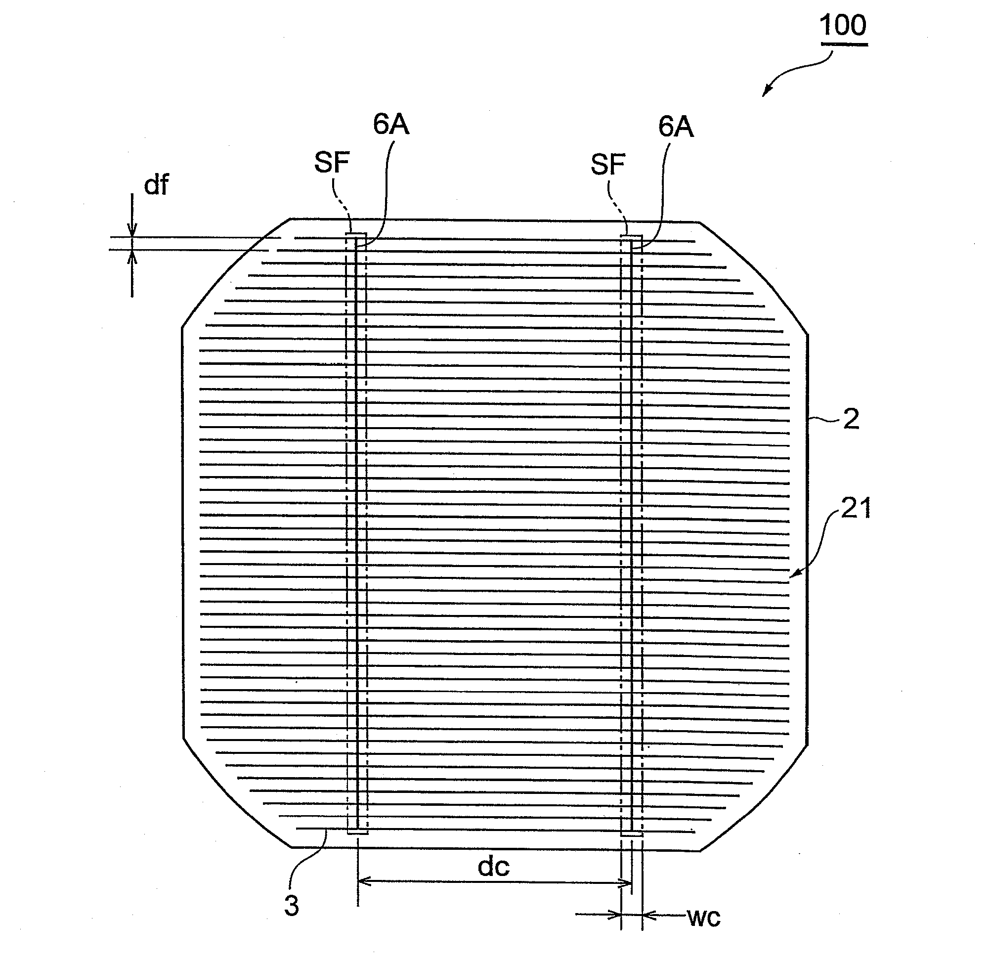
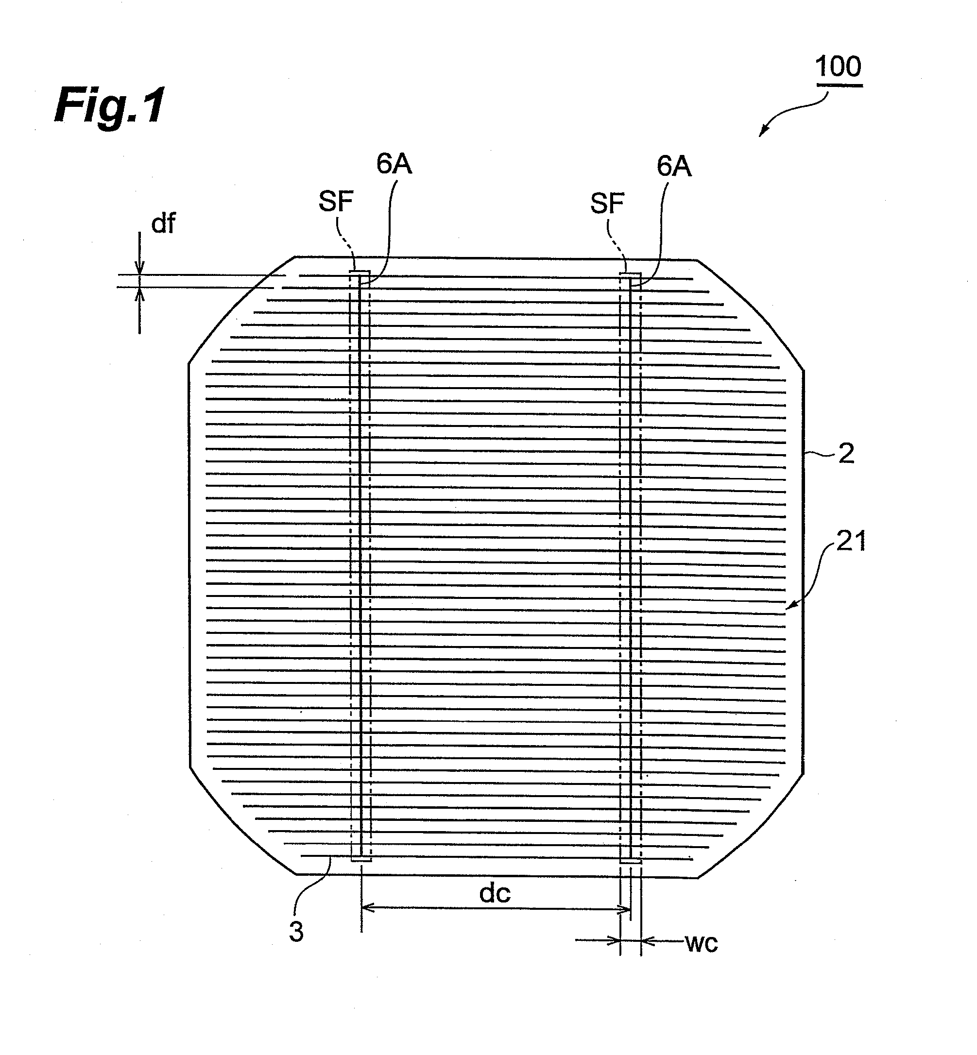
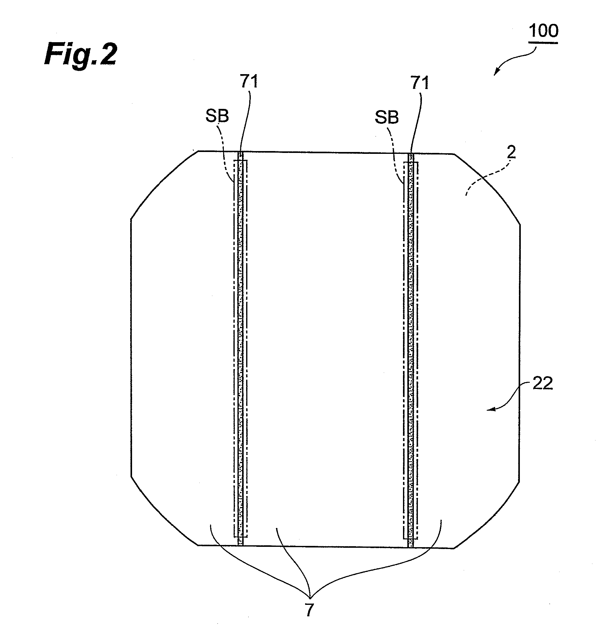
[0030]FIG. 1 is a plan view showing a light receiving surface of a solar battery cell according to a first embodiment of the present invention. FIG. 2 is a bottom view showing a back surface of the solar battery cell in FIG. 1. FIG. 3 is a perspective view showing that a plurality of the solar battery cells in FIG. 1 are connected together. FIG. 4 is a schematic side view of FIG. 3.

[0031]As shown in FIG. 1, a solar battery cell 100 is such that a plurality of the solar battery cells 100 are electrically connected together in series or parallel to form one solar battery module. The solar battery cell 100 includes a substrate 2. The substrate 2 is generally square and has four circu...


PUM

PropertyMeasurementUnit
widthaaaaaaaaaa
widthaaaaaaaaaa
distanceaaaaaaaaaa

Abstract

A solar battery cell and related methodology are provided which enable a TAB wire to be accurately connected to an intended position, thus allowing a possible increase in manufacturing costs to be suppressed. A solar battery cell includes a plurality of finger electrodes arranged on a light receiving surface of a photovoltaic substrate, the light receiving surface having a region of predetermined width to receive a conductive adhesive of a same width as the region. The region is provided with an alignment marking indicating a position where the adhesive is to be applied over the surface, the alignment marking having a cross-dimension in a widthwise direction of the region that is less than the predetermined width.

Description

BACKGROUND OF THE INVENTION[0001]1. Field of the Invention[0002]The present invention relates to a solar battery cell, a solar battery module, a method of making a solar battery cell and a method of making a solar battery module.[0003]2. Related Background Art[0004]In recent years, much attention has been paid to solar batteries as means for solving increasingly serious global warming and fossil energy depletion problems. A solar battery is normally formed by connecting a plurality of solar battery cells together in series or parallel. The solar battery cell includes a plurality of linear electrodes (finger electrodes) arranged in parallel on a front surface (light receiving surface) thereof and formed of Ag in order to provide power. A back surface electrode formed of Al is formed all over a back surface of the solar battery cell. Then, adjacent solar battery cells are connected together by connecting a metal wiring member (TAB wire) to the light receiving surface of one of the adj...

Claims


Application Information

Patent Timeline
Patent Type & Authority Applications(United States)
IPC IPC(8): H01L31/05H01L31/18B32B37/12H01L31/0224
CPCH01L31/022425H01L31/022433Y10T29/49002Y02E10/50Y10T156/10H01L31/0504
Inventor TSURUOKA, YASUOTAKEMURA, KENZOUFUKUSHIMA, NAOKIASAKAWA, YUSUKE
Owner HITACHI CHEM CO LTD
Why Eureka
Try Eureka