
Line Element Lead-Through with Support Structure

a support structure and lead-through technology, applied in the direction of pipes, combustion processes, lighting and heating apparatus, etc., can solve the problems of difficult lead-through openings for cables, pipes and the like, uncertain skilled tradesmen, etc., and achieve the effect of simple installation

Inactive Publication Date: 2012-12-06
HILTI AG
View PDF4 Cites 38 Cited by
  • Summary
  • Abstract
  • Description
  • Claims
  • Application Information

AI Technical Summary

Benefits of technology

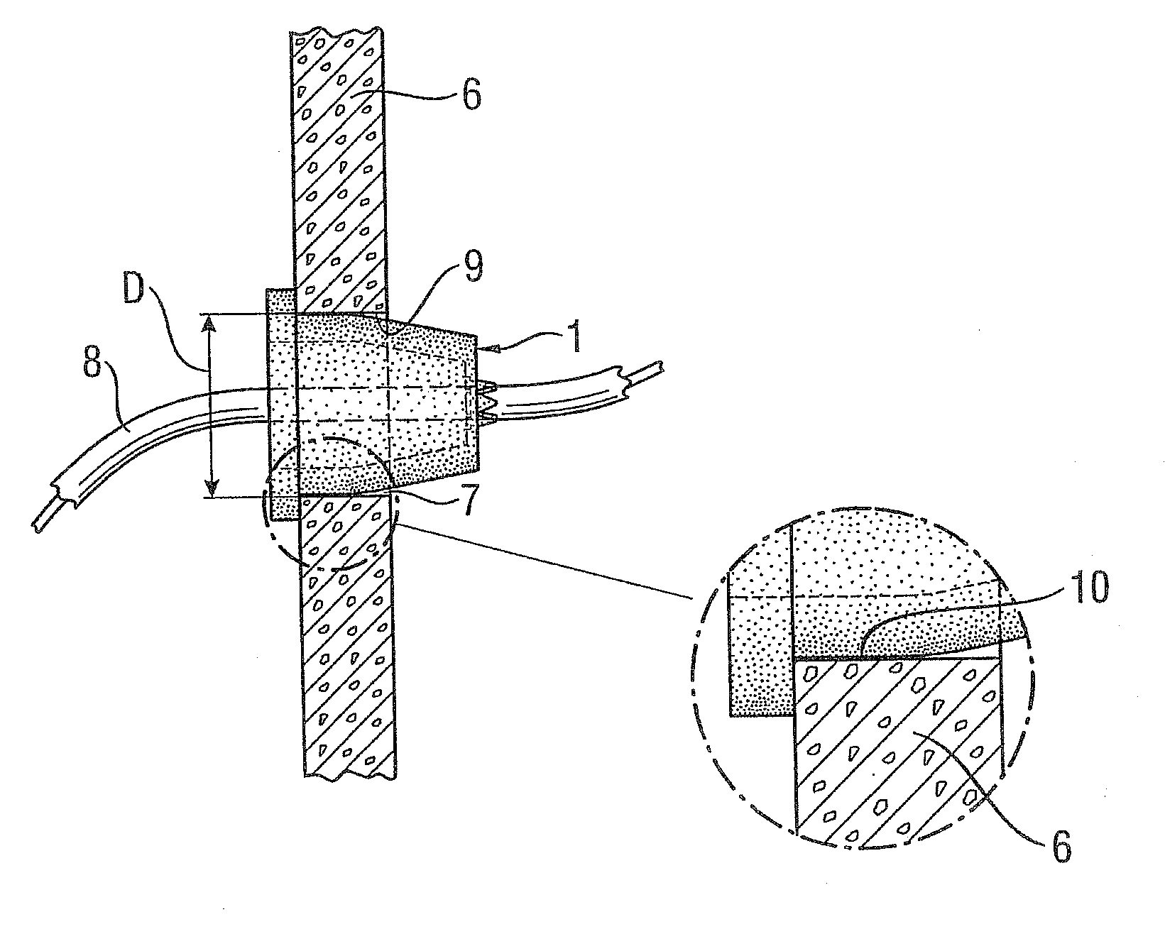
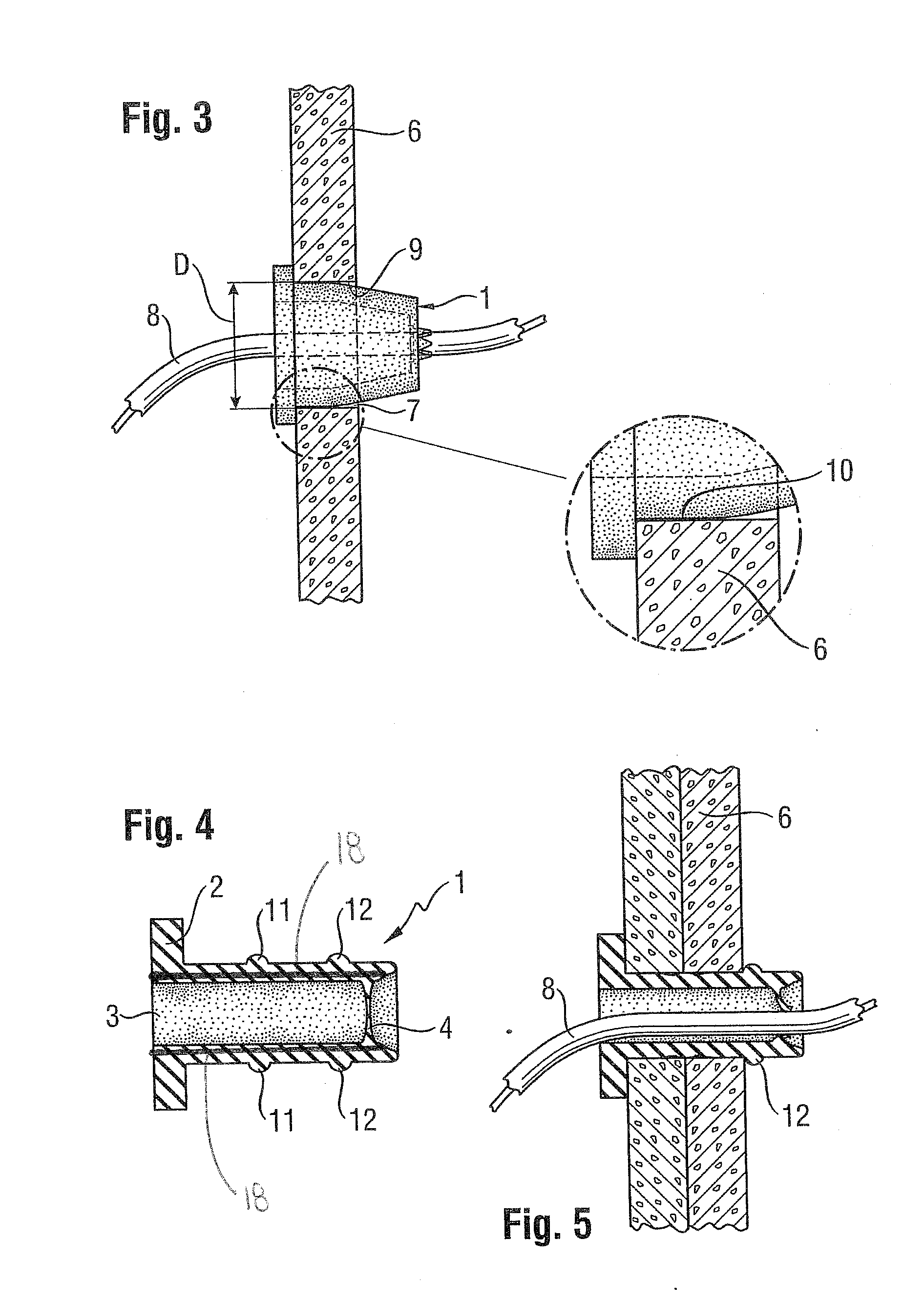
[0013]Some embodiments according to the present invention provide a line element lead-through that is resistant to fire and flue gas for simple installation into one or more paneled drywalls, whereby the line element lead-through can be used in a matching component opening and is also sealed against fire and flue gas when empty. A line element lead-through can be provided with a molded element closed on at least one side of an elastically deformable intumescent material as a sleeve (e.g., configured as a truncated cone or a cylinder) characterized by a criterion that the opening cross section of the sleeve corresponds to maximum 60% of the cross section of the component pass-through.

Problems solved by technology

In the fittings of rooms, the lead-throughs and lead-through openings for cables, pipes and the like are problematic since they were not installed until after completion of the entire installation, i.e., retrofit, and also can only be retrofitted after the routing of the cables and pipes.
However, it is often necessary that lines must be routed long after the installation is complete.
The rules on how all of this must be designed are different, so the skilled tradesman is uncertain during the installation of how the line lead-through must be sealed.
During production of lead-throughs in fire-resistant components that are only equipped with lines much later, the problem resulted that up to the time the openings are equipped they have to be sealed so that they are fire-tight and sealed against flue gas.
To date, this has not been possible using simple devices.
The cable boxes that were previously commonly used are complicated, especially when later fitting them with cables and / or pipes.
The difficulty arises in that the (subsequent) openings have to be sealed against flue gas.
Thus, a considerable amount of work is required for subsequent equipping of the stopper with cables or lines, which makes the system inflexible and susceptible to errors.
When they are equipped with several cables or lines, the problem also results that because of its thickness the material does not seal the gussets and gaps that occur, so these have to additionally be sealed with special sealing compounds.
However, the arrangement itself is not sealed against flue gas, so it cannot be used if the component lead-through is not equipped.
In addition, the arrangement has the disadvantage that equipping it with several long molded parts (line elements) is impossible because of the less flexible sleeve.
Generally, compliance with the 60% rule for cable seals with official approval causes great problems, according to which only up to max.
In practice, this is difficult to evaluate when this limit is reached or exceeded.

Method used


Image

  • Line Element Lead-Through with Support Structure
  • Line Element Lead-Through with Support Structure
  • Line Element Lead-Through with Support Structure

Examples


Embodiment Construction

[0053]In the sense of one or more embodiments of the present invention, the following definitions are used:[0054]“elastically deformable” means that the material of which the line element lead-through is made of is sufficiently elastic so that pressing it together is possible without problems, i.e., without exerting a great deal of force, say by hand, and the line element lead-through again assumes its original shape;[0055]“form fitting” means that the line element lead-through contacts the inner wall of the component lead-through directly not only in one spot but over a certain area and forms a contact surface;[0056]“intumescent material” means an intumescent foam material that carbonizes at temperatures starting at approximately 150° C. and / or the effect of flame with multiple increases in volume; an intumescent material according to one or more embodiments of the present invention that can be used is described, for example, in DE 3917518 or U.S. Pat. No. 3,574,664;[0057]“ash form...


PUM


Abstract

In order to produce a line element lead-through that is resistant to fire and flue gas for simple installation into one or more paneled drywalls, whereby the line element lead-through can be used in a matching component opening and is also sealed against fire and flue gas when empty, a line element lead-through is suggested with a molded element closed on at least one side of an elastically deformable intumescent material as a sleeve, especially formed as a truncated cone or a cylinder, with the criterion that the opening cross section of the sleeve corresponds to maximum 60% of the cross section of the component pass-through. Embedded within the molded element is a support structure.

Description

CROSS-REFERENCE TO RELATED APPLICATIONS[0001]The present application is a continuation-in-part of U.S. patent application Ser. No. 13 / 403,396, filed Feb. 23, 2012, which claims benefit from and priority to German Patent Application No. DE 10 2011 004 575.9, filed Feb. 23, 2011.[0002]The present application is also a continuation-in-part of U.S. patent application Ser. No. 13 / 300,321, filed ______, which claims benefit from and priority to German Patent Application No. DE 10 2010 044 161.9, filed Nov. 19, 2010.[0003]The above-identified applications are hereby incorporated herein by reference in their entirety.BACKGROUND OF THE INVENTION[0004]For fire protection purposes, lead-throughs of line elements, e.g., pipes or cables or the like, through walls or ceilings must be provided with a so-called barrier or a fitting in order to prevent flames and especially smoke and poisonous gases from spreading from room to room or between floors if there is a fire.[0005]In the fittings of rooms,...

Claims


Application Information

Patent Timeline
IPC IPC(8): F23J13/02
CPCH02G3/22H02G3/088F16L5/04
Inventor MUNZENBERGER, HERBERTDREXL, MICHAELKLEIN, MANFRED
Owner HILTI AG
Learn More