
Reducing demand/response effects implementing volt/var control

a technology of demand response and control system, applied in the field of electric power systems, can solve problems such as voltage drop, heated power lines, and wasted energy in power distribution circuits, and achieve the effect of reducing the pre-rebounds of demand response events

Inactive Publication Date: 2012-11-22
GENERAL ELECTRIC CO
View PDF24 Cites 9 Cited by
  • Summary
  • Abstract
  • Description
  • Claims
  • Application Information

AI Technical Summary

Benefits of technology

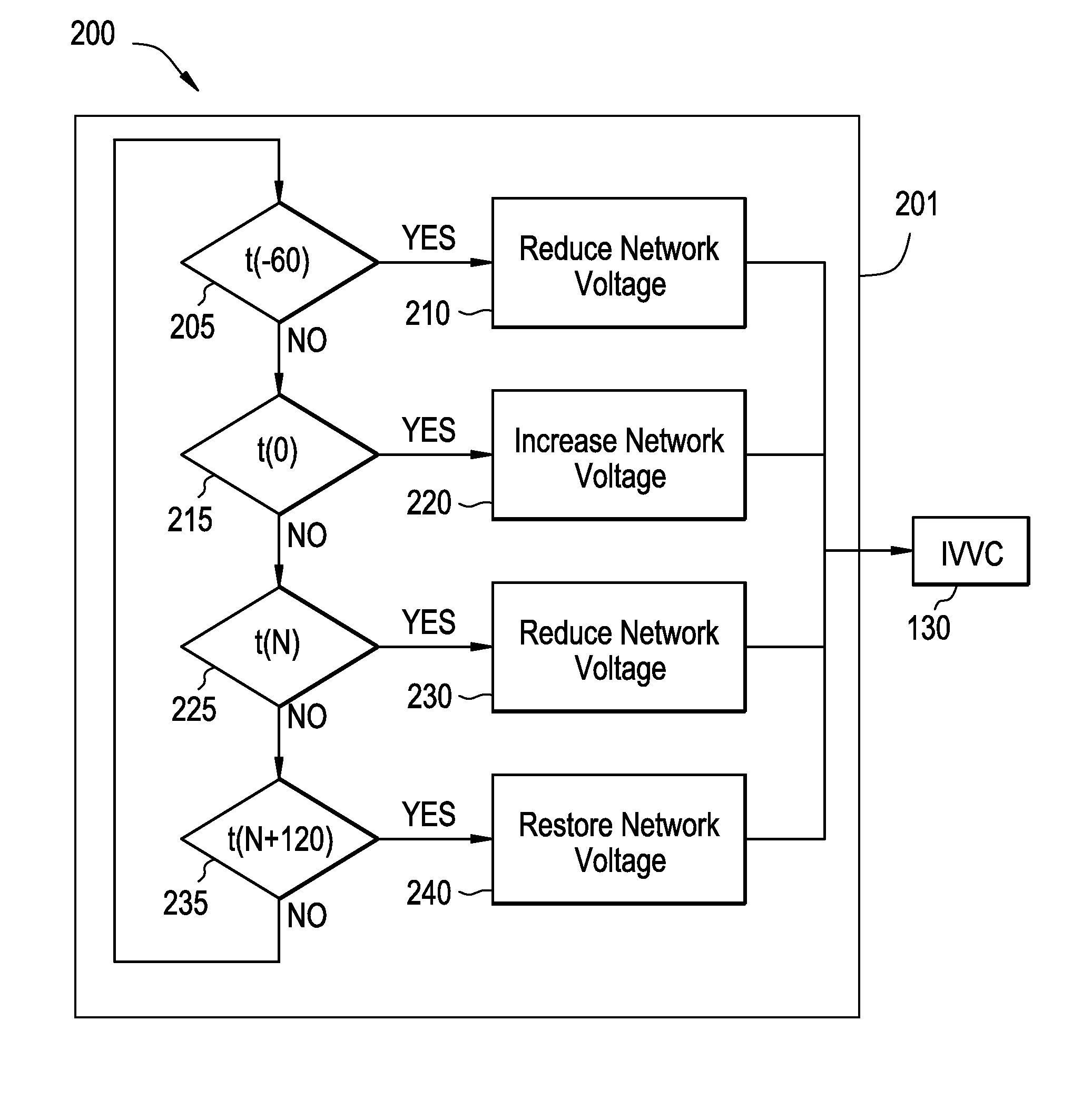
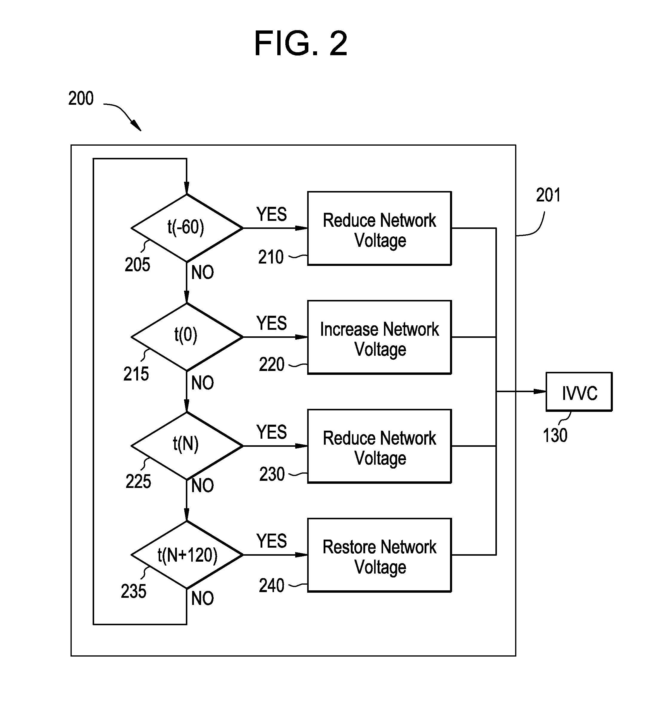
[0004]According to one aspect of the invention, a method for reducing effects of a demand / response event in a power distribution network is described. The method can include identifying a load profile in the power distribution network, in response to detecting a peak in the load profile, decreasing voltage in the power distribution network and in response to a detecting a trough in the load profile, increasing the voltage in the power distribution network.
[0005]According to another aspect of the invention, a computer program product for reducing effects of a demand / response event in a power distribution network is described. The computer program product can include a non-transitory computer readable medium having instructions for causing a computer to implement a method. The method can include identifying a load profile in the power distribution network, in response to detecting a peak in the load profile, decreasing voltage in the power distribution network and in response to a detecting a trough in the load profile, increasing the voltage in the power distribution network.
[0006]According to yet another aspect of the invention, a system for reducing effects of a demand / response event in a power distribution network is described. The system can include a demand response management system and a demand response management system demand event dispatcher process residing on the demand response management system, and configured for reducing voltage in the power distribution network at specified times and actively increasing the voltage in the network during additional specified times to reduce a load difference between peaks and troughs during the demand response event.

Problems solved by technology

This phenomena leads to an extra current in the power lines, which can cause wasted energy in the form of heated power lines, as well as voltage drops in the power distribution circuits.
Demand response events can cause significant increases in the overall load profile of the power distribution circuits before and after the demand response event.

Method used


Image

  • Reducing demand/response effects implementing volt/var control
  • Reducing demand/response effects implementing volt/var control
  • Reducing demand/response effects implementing volt/var control

Examples


Embodiment Construction

[0014]FIG. 1 illustrates an exemplary system 100 for reducing demand response event pre-rebounds and post-rebounds implementing volt / VAR support. It will be appreciated that the system 100 is a part of a larger power distribution network controlled by a power utility. In exemplary embodiments, the system 100 can include a demand response management system (DRMS) 110, which is a utility operational system responsible for creating and managing demand response events that control end consumer electric power consumption. In exemplary embodiments, demand response events can be controlled by directly controlling end consumer devices (i.e., direct load control), or by sending variable power rates to end consumer devices (i.e., pricing control) to shift consumer electric power consumption behavior. For example, pre-rebounds and post-rebounds can be controlled by anticipating a pre-rebound and informing a consumer that at a particular time of day, the power rate cost will increase. The power...


PUM


Abstract

A method for reducing effects of a demand / response event in a power distribution network can include identifying a load profile in the power distribution network, in response to detecting a peak in the load profile, decreasing voltage in the power distribution network and in response to a detecting a trough in the load profile, increasing the voltage in the power distribution network.

Description

BACKGROUND OF THE INVENTION[0001]The subject matter disclosed herein relates to electric power systems and more particularly to reduction of demand / response effects implementing volt / VAR control systems and methods.[0002]Reactive power occurs when apparatuses with inductance or capacitance return power to the power plant supplying the power to the apparatus. For example, an electrical appliance contains inductance and capacitance. During portions of the alternating current (AC) cycle, the appliance stores energy, and during other portions of the AC cycle, the appliance returns the energy. As such, electrical energy from the appliance periodically returns to the power plant, and the energy flows back and forth across the power lines. This phenomena leads to an extra current in the power lines, which can cause wasted energy in the form of heated power lines, as well as voltage drops in the power distribution circuits. “VAR” is volt-amperes-reactive and is the term used to describe rea...

Claims


Application Information

Patent Timeline
Patent Type & Authority Applications(United States)
IPC IPC(8): G06F1/28
CPCH02J3/16Y02E40/34Y04S10/22Y04S10/24Y04S40/124Y02E40/74H02J3/1828H02J13/0062H02J13/0079H02J13/0086Y02E60/7838Y02E60/726H02J13/00017H02J13/00016H02J13/00028H02J13/00034Y02E40/30Y02E40/70Y02E60/00Y04S10/00
Inventor SCHMID, JAMES JOSEPH
Owner GENERAL ELECTRIC CO
Learn More