Eureka AIR delivers breakthrough ideas for toughest innovation challenges, trusted by R&D personnel around the world.

System for Controlling Torque Distribution

a torque distribution and torque technology, applied in the direction of interengaging clutches, couplings, gearing, etc., can solve the problems of adversely affecting the reliance on indirect determination of traction loss, and the acceleration sensor not directly detecting the loss of traction, so as to improve the cruising stability of the vehicl

Inactive Publication Date: 2012-11-22
GANCHEV STILIYAN TSONEV
View PDF1 Cites 3 Cited by
  • Summary
  • Abstract
  • Description
  • Claims
  • Application Information

AI Technical Summary

Benefits of technology

[0009]Accordingly, it is an object of the invention to directly detect changes in the traction between the wheels of the continuously engaged primary driving axle and the road, thereby ensuring an accurate quantitative assessment of traction.
[0010]It is another object of the invention to minimize the delay between detection of traction loss and the execution of corrective measures to correct the traction loss.
[0012]It is a further object of the invention to provide a system for controlling torque distribution that improves cruising stability of a vehicle.

Problems solved by technology

The speed and acceleration sensors do not directly detect loss of traction.
Therefore, calculation and determination of traction loss is done after loss of traction has already occurred, thereby adversely affecting cruising stability of the vehicle.
A disadvantage of these prior art torque distributors is the delay caused by the reliance on the indirect determination of traction loss.
However, the detection of such discrepancies by the ABS sensors represents a delayed detection of traction loss.
Another disadvantage of electronically controlled torque distribution systems is the complete absence of quantitative data regarding the magnitude of the lost traction.

Method used


Image

  • System for Controlling Torque Distribution
  • System for Controlling Torque Distribution
  • System for Controlling Torque Distribution

Examples


Embodiment Construction

[0020]Referring to the drawings, a description will be made with regards to preferred embodiments of a torque distribution control system according to the present invention.

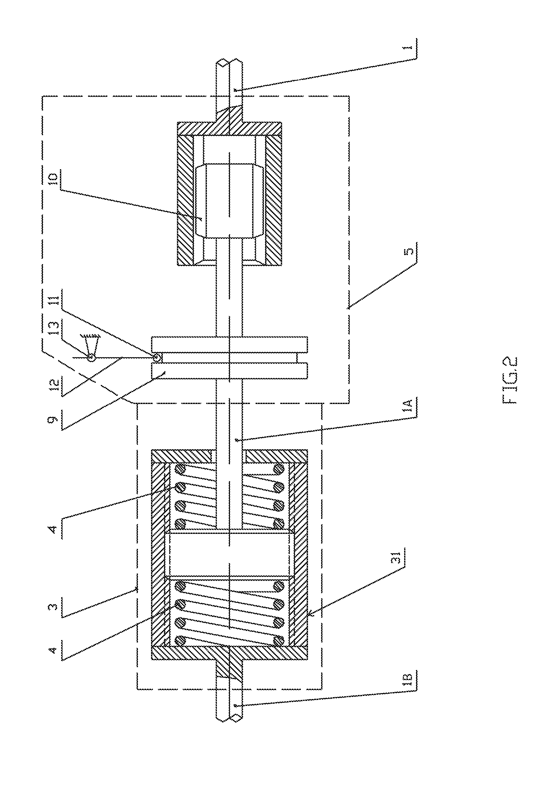
[0021]FIG. 1 shows a first preferred embodiment of the present invention. A drive source 24, which can include a transmission and an engine (not shown), generates torque and transfers the torque to a first shaft portion 1A when a primary clutch (not shown) is engaged. The torque causes the first shaft portion 1A to rotate about its longitudinal axis. In a torsion unit 3, deformable elastic elements 4 connect the first shaft portion 1A to a housing 31 located at one end of a second shaft portion 1B. The other end of second shaft portion 1B is mechanically connected to a primary driving axle 2 that is continuously engaged to the drive source, the primary driving axle 2 equipped with rotatably mounted primary driving wheels 32. As the first shaft portion 1A rotates, torque is transferred to the second shaft portion ...


PUM


Abstract

A torque distribution control system comprises a torsion unit for detecting traction on wheels of a primary driving axle that is continuously engaged with a drive source or a source of torque power. The amount of traction detected is converted to a signal with variable signal strength, the signal strength correlating to the amount of traction detected by the torsion unit. The signal strength capable of being adjusted automatically based on select parameters and / or manually based on a driver's input. And, in response to the signal, actuators engage and control operations of the vehicle such as the drive source, a braking system, and / or an axle clutch, with the level of engagement dependent upon the signal strength.

Description

BACKGROUND OF THE INVENTION[0001]1. Related Applications[0002]This application is a continuation-in-part application of U.S. patent application Ser. No. 12 / 280,556, filed Dec. 22, 2008, which is the National Stage of International Application No. PCT / BG2007 / 000003, filed Feb. 22, 2007. This application claims benefit of Bulgarian Patent Application No. 109454, filed Feb. 24, 2006. The above applications are incorporated by reference herein.[0003]2. Field of Invention[0004]The invention relates to a system for controlling torque distribution applicable in mechanical engineering. This torque distribution control system can be used in motor vehicles or in applications requiring the automatic control of torque in functionally connected objects.RELATED ART[0005]An increasing number of motor vehicles incorporate torque distribution control systems to provide greater vehicle stability and increased fuel efficiency. The effectiveness of these torque distribution control systems depends prim...

Claims


Application Information

Patent Timeline
Patent Type & Authority Applications(United States)
IPC IPC(8): B60W10/196B60W10/02B60K17/346F16F1/48F16H48/32F16H48/34
CPCB60K17/3505B60K23/0808Y10T477/78Y10T477/745B60W2520/263F16D23/12F16D43/216F16D3/76F16D11/14F16D13/52F16D47/02B60K17/02B60K17/344B60K17/35B60K17/34
Inventor GANCHEV, STILIYAN TSONEV
Owner GANCHEV STILIYAN TSONEV
Why Eureka
Eureka Blog
Learn More