
Large effective area optical fibers

a technology of optical fibers and effective areas, applied in the field of optical fibers, can solve the problems of fiber nonlinearity, limiting the speed of optical fibers, affecting the performance of optical fibers, etc., and achieves the effects of reducing the number of optical fibers, and improving the quality of optical fibers

Inactive Publication Date: 2012-11-22
CORNING INC
View PDF2 Cites 16 Cited by
  • Summary
  • Abstract
  • Description
  • Claims
  • Application Information

AI Technical Summary

Benefits of technology

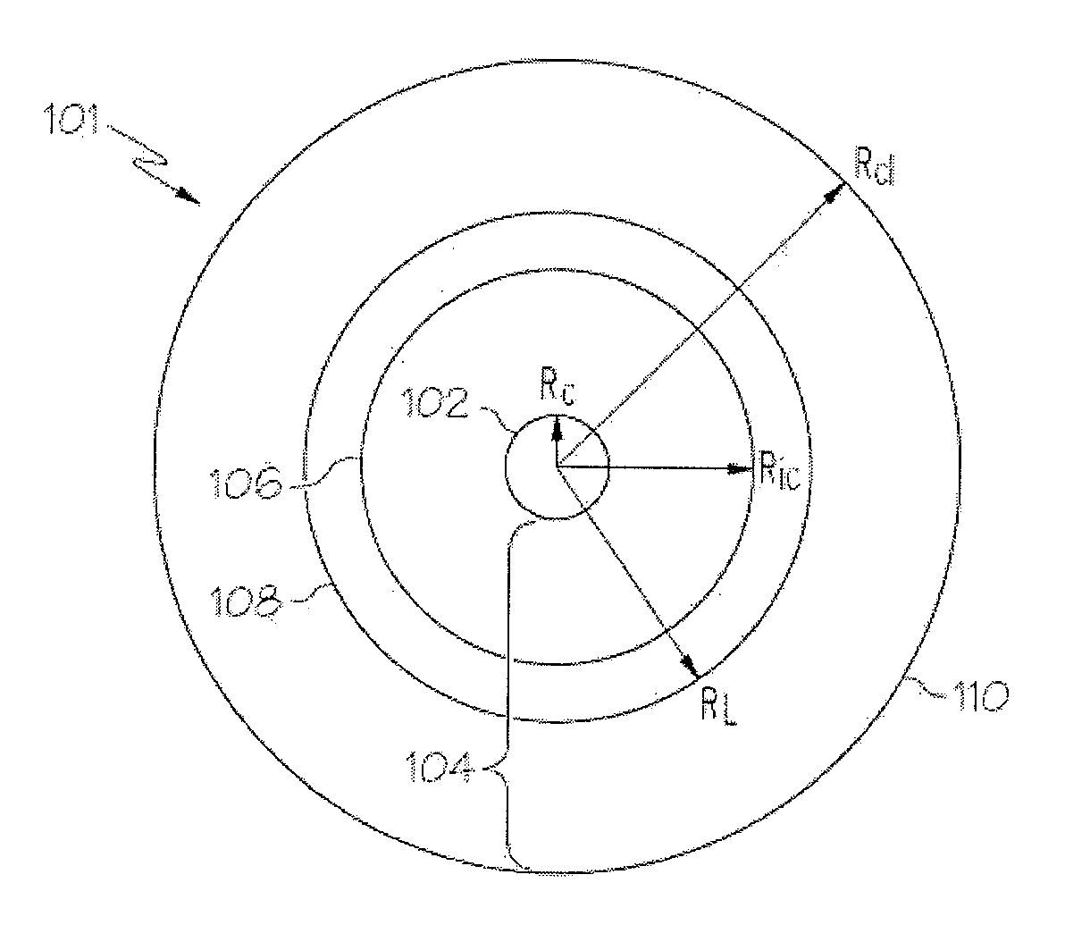
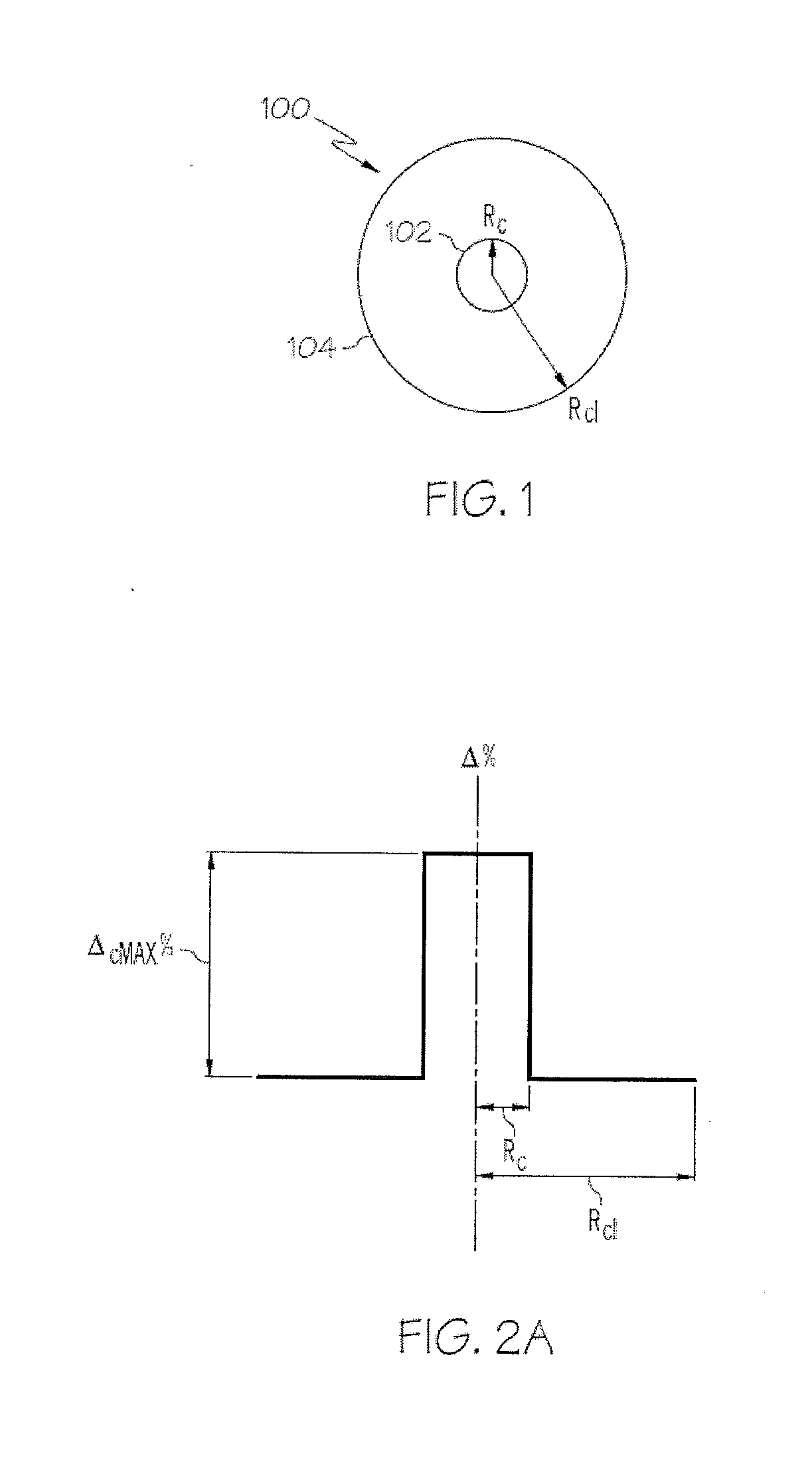
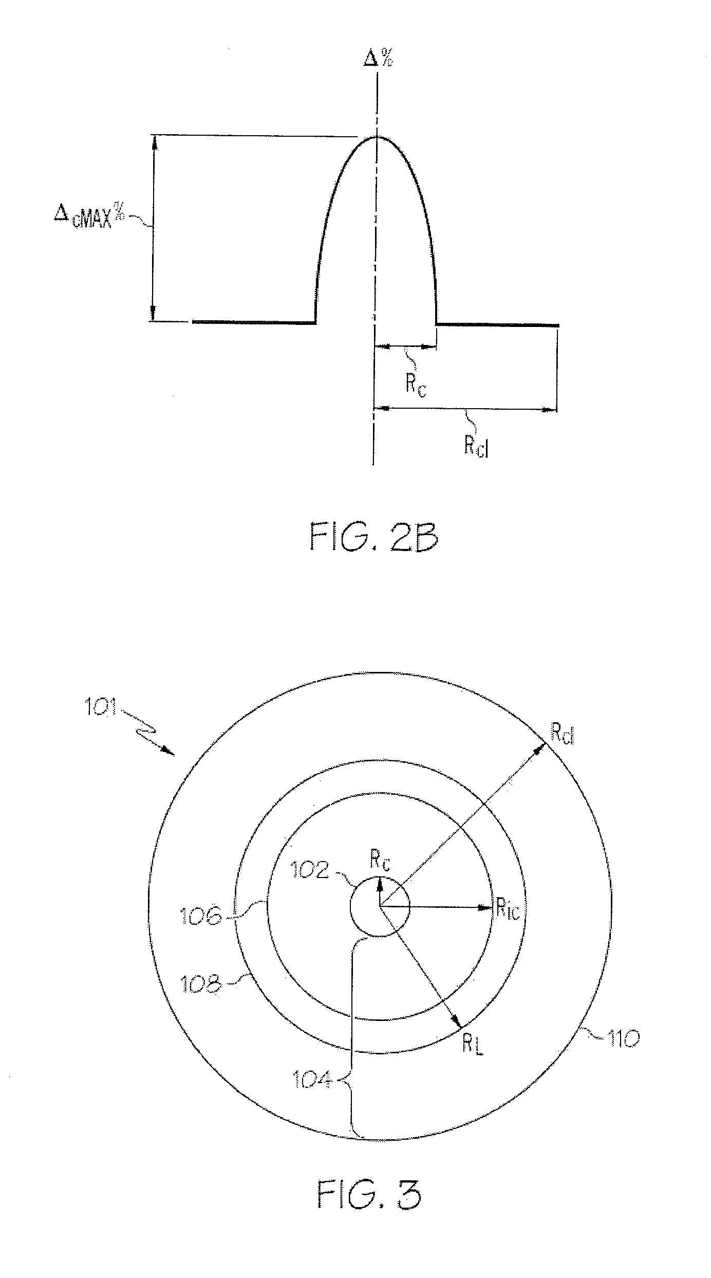
[0008]According to one embodiment, an optical fiber may include a glass core and a glass cladding surrounding and in direct contact with the glass core. The glass core may have a radius Rc, from about 12 μm to about 50 μm (for example, 16 μm>Rc>50 μm) and a graded refractive index profile with an alpha value greater than or equal to about 1.0 and less than about 10 at a wavelength of 1550 nm. The maximum relative refractive index ΔcMAX% of the core may be from about 0.2% to about 0.75% relative to th

Problems solved by technology

In general, fiber nonlinearity is a fundamental limiting factor to such high speed, long haul, WDM telecommunications systems.
Each of these non-linear effects can cause the degradation of optical signals propagating in the WDM telecommunications systems.
However, an increase in the effective area of an optical fiber typically results in an increase in the induced bending losses (both micro and macro) and, as a result, the attenuation of the optical signal propagating in the optical fiber.
Accordingly, the ability to reduce the non-linearity of conventional single-mode transmission optical fibers by increasing the effective area of the fiber is limited by the corresponding increase in bending losses for the fundamental mode of the optical signal propagating in the fiber.

Method used


Image

  • Large effective area optical fibers
  • Large effective area optical fibers
  • Large effective area optical fibers

Examples


examples

[0058]The invention will be further clarified by the following examples.

[0059]A plurality of optical fibers were mathematically modeled to determine the effect of variations of ΔcMAX% and core radius on the effective area and pin array bending losses at 1550 nm. Table 1 contains data for comparative and inventive optical fibers with step refractive index profiles. Specifically, comparative Example C1 was a single mode fiber with a core having a step refractive index profile, a ΔcMAX% valued of 0.20% and a radius of 6 μm which results in an effective area of 153.9 μm2 at 1550 nm and a pin array bending loss of 65 dB at 1550 nm. Examples 2-8 were also modeled with a core having a step refractive index profile. However, in examples 2-8 the theoretical cutoff wavelength was adjusted by increasing ΔcMAX% and varying the radius of the core. As shown in Table 1, Examples 2-8 each supported the propagation and transmission of at least 2 modes and each had an effective area of greater than a...


PUM


Abstract

Large effective area optical fibers are disclosed. In one embodiment, an optical fiber includes a glass core and a glass cladding surrounding and in direct contact with the glass core. The glass core may include a radius Rc from about 12 μm to about 50 μm; a graded refractive index profile with an alpha value greater than or equal to about 1.0 and less than about 10 at a wavelength of 1550 nm; and a maximum relative refractive index ΔcMAX% from about 0.2% to about 0.75% relative to the glass cladding. An effective area of the core may be greater than or equal to about 150 μm2 such that the core supports the propagation and transmission of an optical signal with X modes at a wavelength of 1550 nm, wherein X is an integer greater than 1 and less than or equal to 110. The glass cladding may include a maximum relative refractive index Δc1MAX% such that ΔcMAX%>Δc1MAX%. The optical fiber has an RMS pulse broadening of less than or equal to about 0.15 ns / km at a wavelength of 1550 nm.

Description

CROSS-REFERENCE TO RELATED APPLICATION[0001]This application claims the benefit of priority under 35 U.S.C. §119 of U.S. Provisional Application Ser. No. 61 / 487,351 filed on May 18, 2011 the content of which is relied upon and incorporated herein by reference in its entirety.BACKGROUND[0002]1. Field[0003]The present specification generally relates to optical fibers and, more specifically, to optical fibers with large effective areas and reduced non-linearity.[0004]2. Technical Background[0005]Optical amplifiers and wavelength division multiplexing (WDM) techniques are typically utilized in optical telecommunications systems that provide high power transmissions over long distances. The definition of high power and long distances is meaningful only in the context of a particular telecommunications system wherein a bit rate, a bit error rate, a multiplexing scheme, and perhaps optical amplifiers are specified. In general, fiber nonlinearity is a fundamental limiting factor to such hig...

Claims


Application Information

Patent Timeline
IPC IPC(8): G02B6/028G02B6/02
CPCG02B6/02019G02B6/0365G02B6/03627G02B6/0288
Inventor LI, MING-JUN
Owner CORNING INC
Learn More