Robot control system, robot system and program

a robot and control system technology, applied in the field of robot control system, a robot system and a program, can solve the problems of visual servoing, robots cannot be controlled, and obstacles to the introduction of robots

Inactive Publication Date: 2012-11-22
SEIKO EPSON CORP
View PDF3 Cites 38 Cited by
  • Summary
  • Abstract
  • Description
  • Claims
  • Application Information

AI Technical Summary

Benefits of technology

[0011]An advantage of some aspects of the invention is to provide a robot control system, a robot system and a program or the like which can perform visual servoing using an image with a marker set thereon.
[0012]Another advantage of some aspects of the invention is to provide a robot control system, a robot system and a program or the like in which a marker and a mask image are set on a workpiece and a hand or the like and visual servoing is performed using these images, thus restraining the cost of preparing reference images and also restraining the processing load in order to enable calculation of an effective control signal even when the workpiece is at a predetermined distance or farther from the hand.

Problems solved by technology

However, accurate calibration is a prerequisite for positioning robots and this creates a barrier to the introduction of robots.
Meanwhile, visual servoing has a downside that a robot cannot be controlled unless the robot stands within a range that can be captured by a camera.
In visual servoing, depending on the image used, image processing may not finish within an estimated period of time and sending of a control signal may be delayed, and when a robot is at a predetermined distance or farther from a target position, image processing may fail and result in inability to generate an effective control signal.
Moreover, when the use of a multipurpose robot capable of handling various kinds of works is assumed, it is difficult to prepare necessary reference images corresponding to all combinations of different workpieces and tools.

Method used


Image

  • Robot control system, robot system and program
  • Robot control system, robot system and program
  • Robot control system, robot system and program

Examples


Embodiment Construction

[0046]Hereinafter, an embodiment will be described. First, an example of a system configuration according to this embodiment will be described. Next, a specific example of this embodiment will be described. Afterwards, details of processing in this embodiment will be described with reference to the flowcharts. The following embodiment is not intended to unduly limit the content of the invention described in the accompanying claims. Not all the elements of the configuration described in the embodiment are necessarily essential element of the invention.

1. Example of System Configuration

1.1 Example of Configuration of Robot System

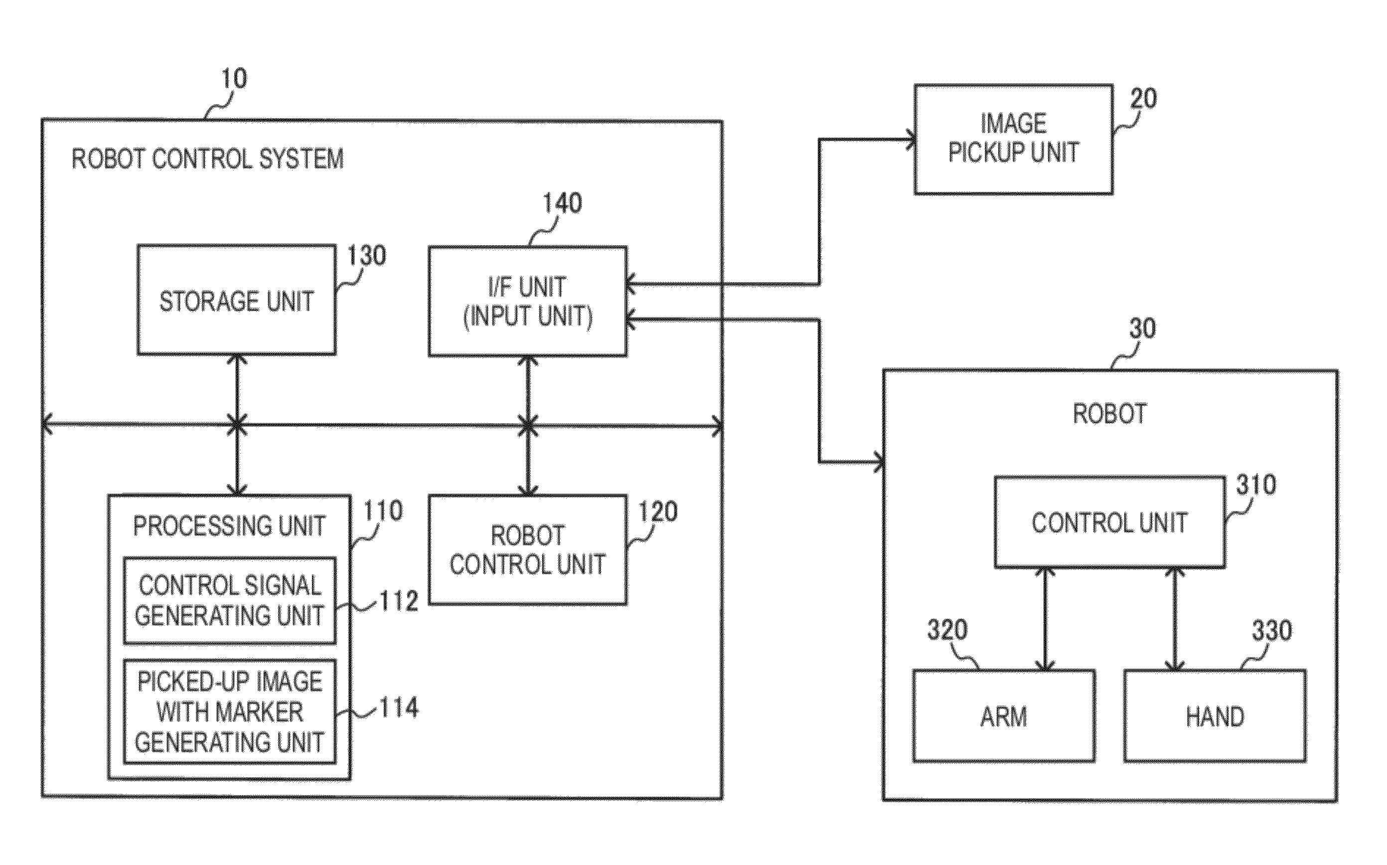
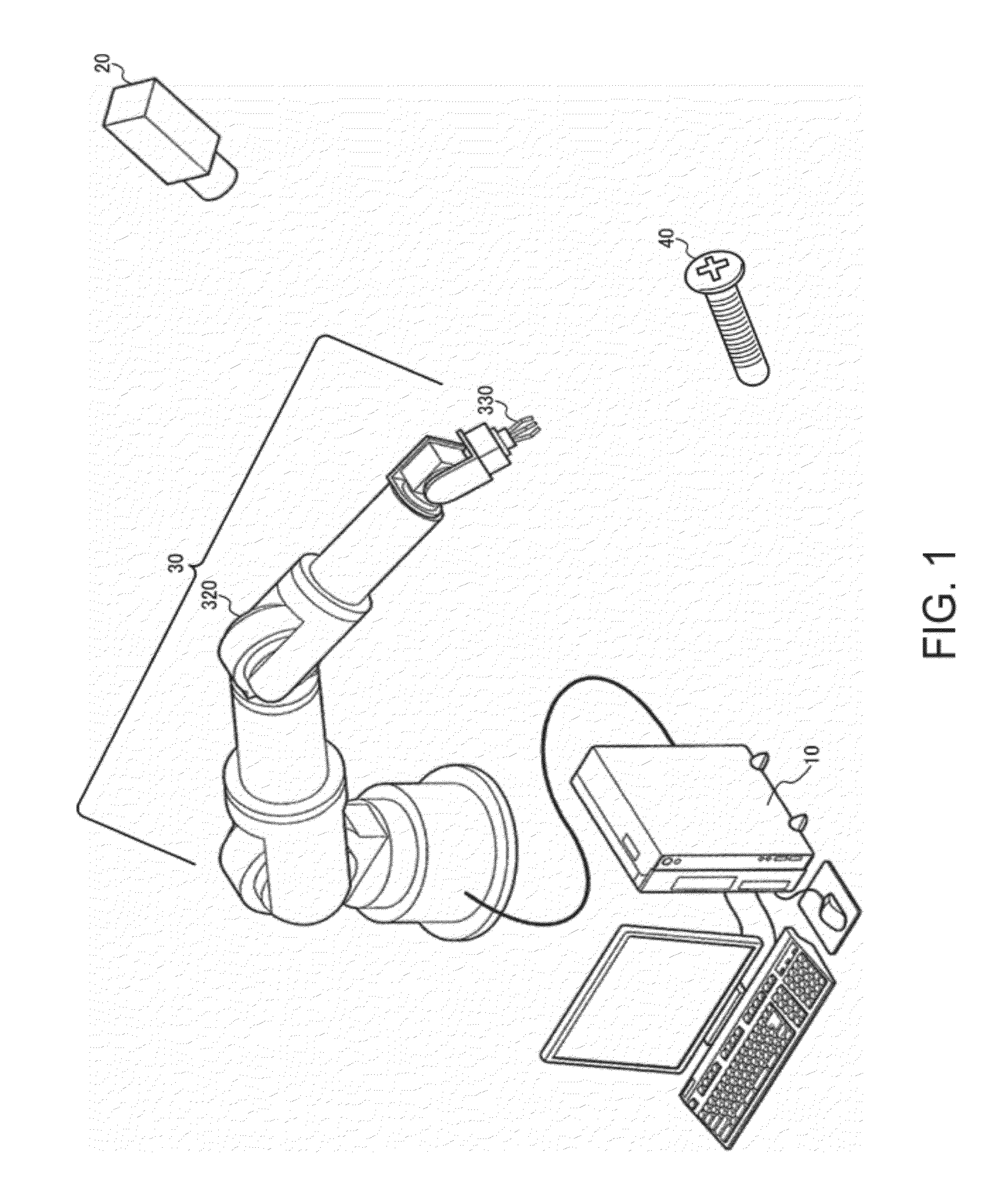
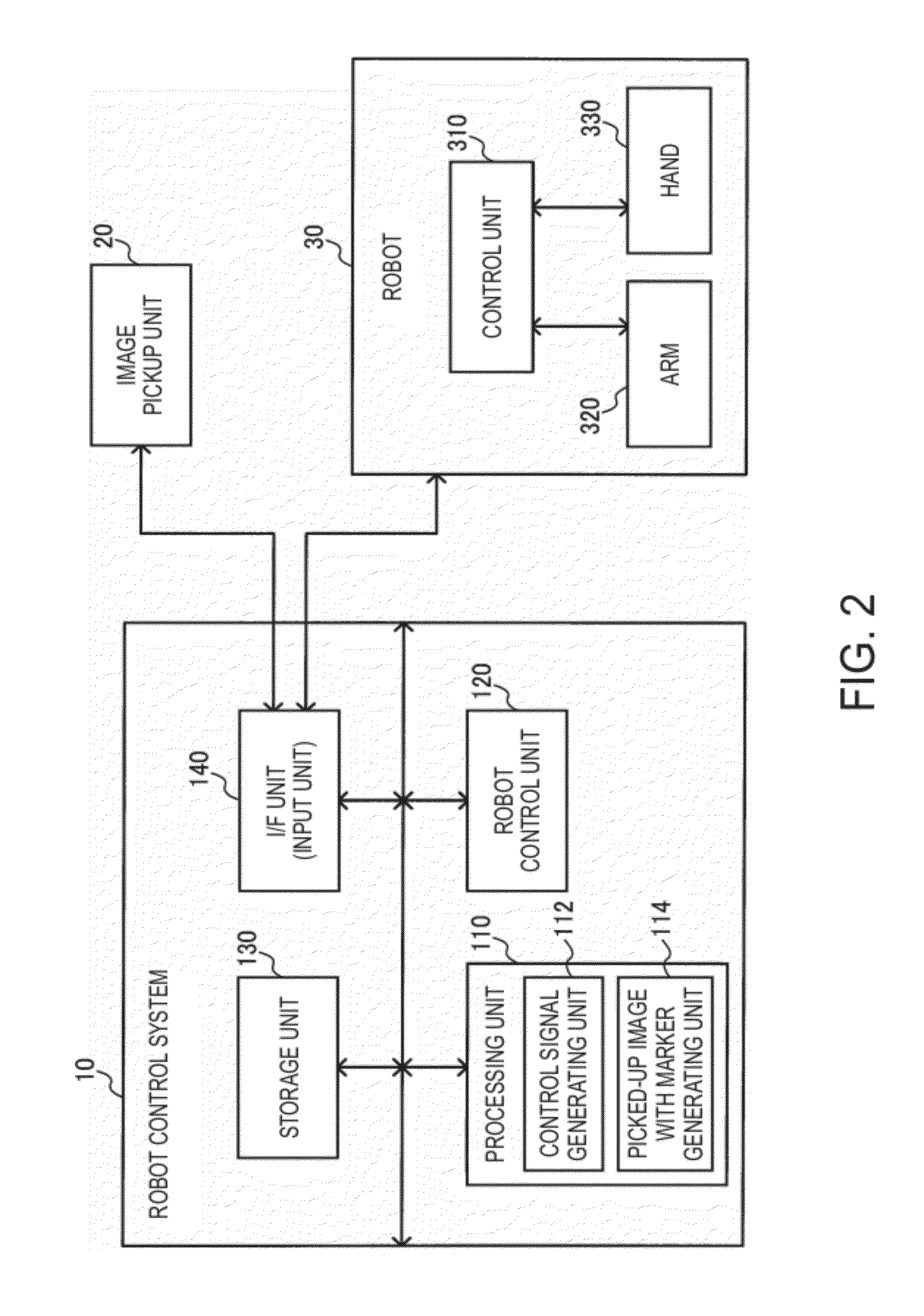
[0047]An example of the configuration of a robot system according to this embodiment is shown in FIG. 1. The robot system includes a robot control system 10, an image pickup unit 20, and a robot 30. However, the robot system is not limited to the configuration of FIG. 1 and various modified embodiments are possible such as omitting one or some of the component...


PUM


Abstract

A robot control system includes a processing unit which performs visual servoing based on a reference image and a picked-up image, a robot control unit which controls a robot based on a control signal, and a storage unit which stores the reference image and a marker. The storage unit stores, as the reference image, a reference image with marker in which the marker is set in an area of a workpiece or a hand of the robot. The processing unit generates, based on the picked-up image, a picked-up image with marker in which the marker is set in an area of the workpiece or the hand of the robot, performs visual servoing based on the reference image with marker and the picked-up image with marker, generates the control signal, and outputs the control signal to the robot control unit.

Description

BACKGROUND[0001]1. Technical Field[0002]The present invention relates to a robot control system, a robot system and a program or the like.[0003]2. Related Art[0004]Recently, industrial robots are increasingly introduced at production sites in order to mechanize and automate works which are previously carried out by humans. However, accurate calibration is a prerequisite for positioning robots and this creates a barrier to the introduction of robots.[0005]Now, visual servoing is used as a technique for positioning a robot. Visual servoing is a technique of controlling a robot based on the difference between a reference image (goal image, target image) and a picked-up image (present image). A type of visual servoing is advantageous in that accuracy in calibration is not required and therefore draws attention as a technique that reduces the barrier to the introduction of robots.[0006]Meanwhile, visual servoing has a downside that a robot cannot be controlled unless the robot stands wit...

Claims


Application Information

Patent Timeline
Patent Type & Authority Applications(United States)
IPC IPC(8): G06K9/00
CPCB25J5/007G05B2219/39393G05B2219/39391B25J9/1697
Inventor MATSUMOTO, SHIGEYUKI
Owner SEIKO EPSON CORP
Why Eureka
Try Eureka