
Distance measurement device and distance measurement method

a technology of distance measurement and distance measurement method, which is applied in the direction of distance measurement, instruments, television systems, etc., can solve the problem of high energy consumption of light sources that cannot be ignored, and achieve the effect of convenient suitably executed

Inactive Publication Date: 2012-11-22
TOYOTA JIDOSHA KK
View PDF5 Cites 22 Cited by
  • Summary
  • Abstract
  • Description
  • Claims
  • Application Information

AI Technical Summary

Benefits of technology

The present invention provides a distance measurement device that can measure the distance between the device and a target using a lens and a camera. The device includes image formation relative quantity calculating means, storing means, and distance calculating means. The device can accurately measure the distance to the target by calculating the image formation relative quantities of the light emitted from the target and the distance between the lens and the image. This allows for precise distance measurement even when the device is mounted on a vehicle. The invention simplifies the structure of the device and reduces the energy consumption of the light source.

Problems solved by technology

Accordingly, energy consumed by the light source is so high that it cannot be ignored.

Method used


Image

  • Distance measurement device and distance measurement method
  • Distance measurement device and distance measurement method
  • Distance measurement device and distance measurement method

Examples


first embodiment

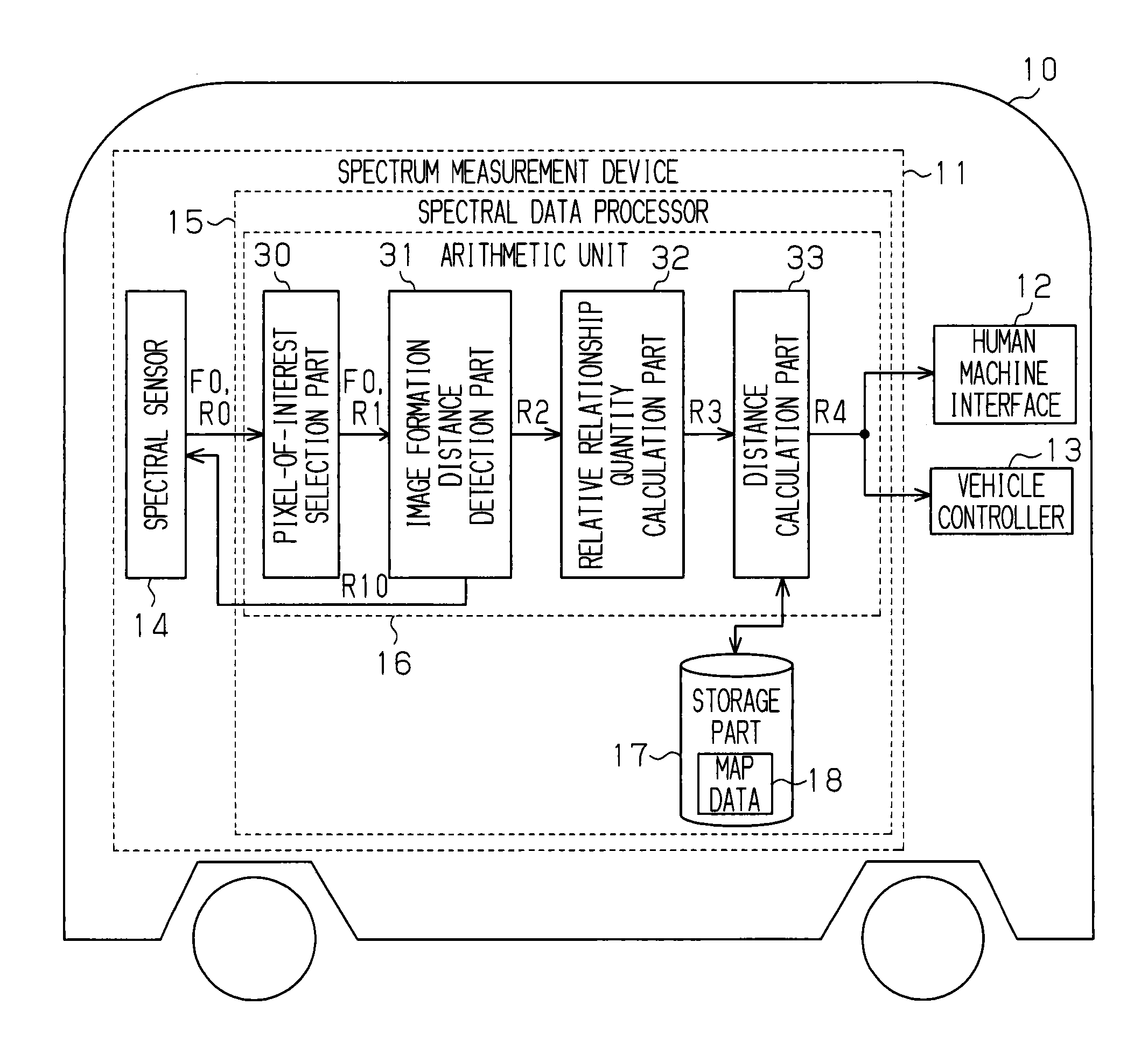
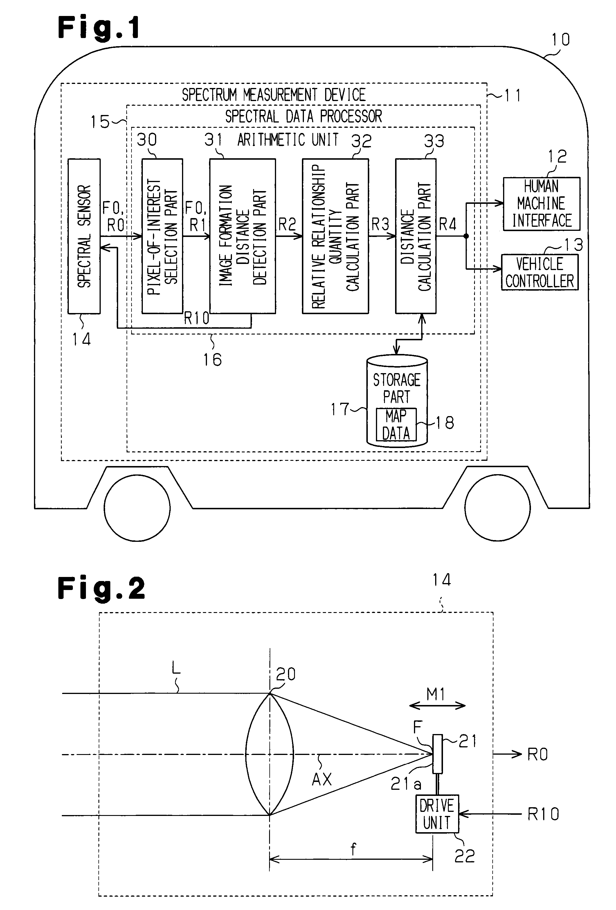
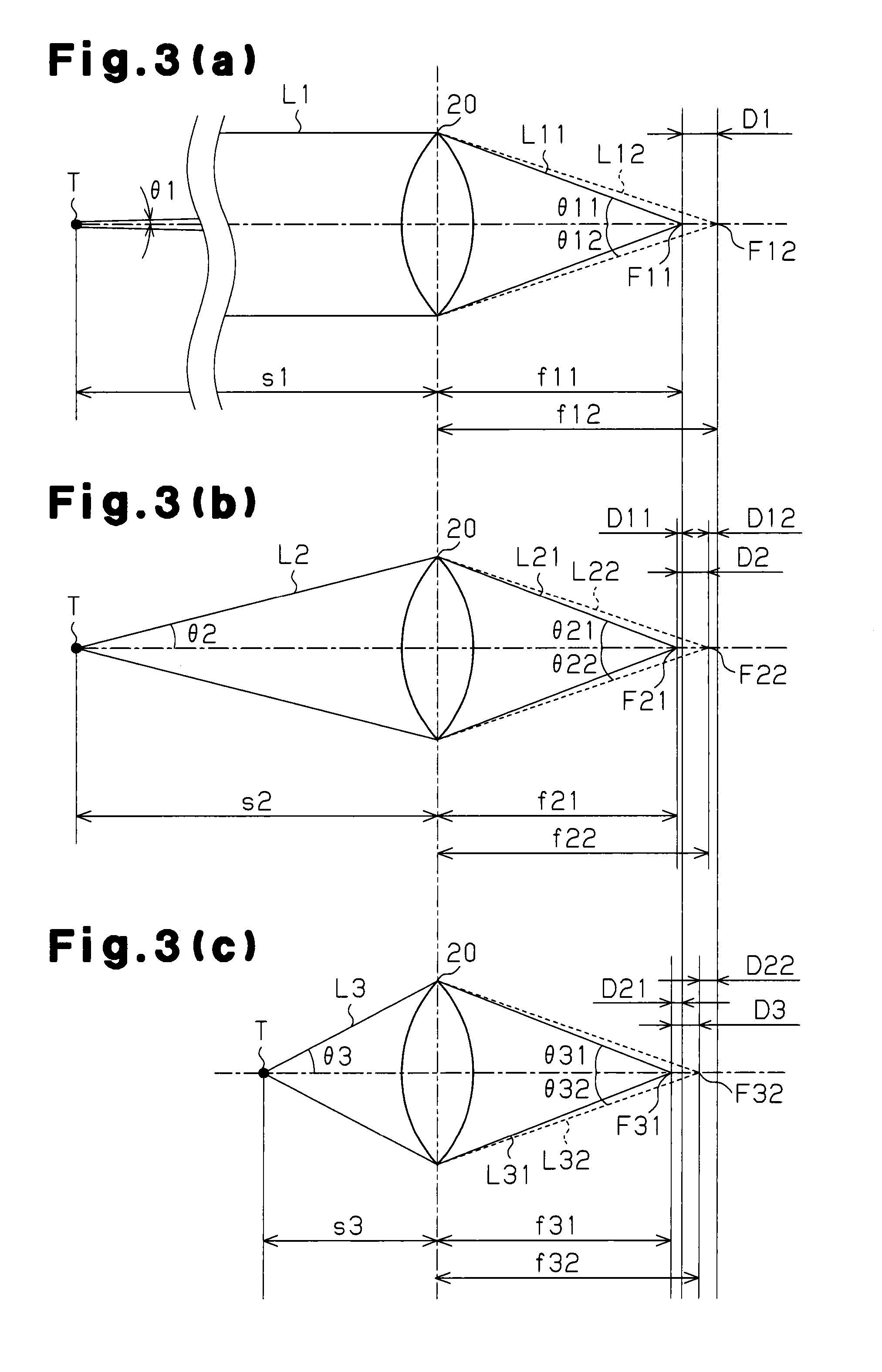
[0052]FIGS. 1 to 6 illustrate a spectrum measurement device 11 according to a first embodiment, which a distance measurement device of the present invention. As shown in FIG. 1, the spectrum measurement device 11 is mounted on a vehicle 10, which is a movable body. That is, FIG. 1 is a block diagram schematically showing the system configuration for the spectrum measurement device 11, which is the distance measurement device mounted on the vehicle 10, which is a movable body.

[0053]In recent years, a technique has been considered for practical application that identifies a measurement target present in the surrounding environment of a spectral sensor, from multispectral data including an invisible optical region measured by the spectral sensor, and provides various kinds of support information to a driver in accordance with the identified measurement target or a state of the measurement target. For example, a drive support device that has been examined for practical application in a ...

second embodiment

[0108]FIGS. 7 to 9 illustrate a spectrum measurement device according to a second embodiment, which shows the distance measurement device according to the present invention. FIG. 7 schematically shows the structure of a spectral sensor 14. FIG. 8 schematically shows a case in which the image of a light having a wavelength of 400 nm is formed. FIG. 9(a) shows a case in which the image of a light having a wavelength of 800 nm is not formed on the image formation plane 21a, and FIG. 9(b) shows a case in which the image is formed on the image formation plane 21a. In this embodiment, the structure of the spectral sensor 14 is that the image formation plane 21a is not linearly moved but rotatably moved, and this rotational movement is different from the structure of the first embodiment. The other structure other than the above is similar to the first embodiment, and therefore different points from the first embodiment will be mainly described, and same numbers are assigned to the same co...


PUM


Abstract

A distance measurement device measures target distances to a measurement target by optically detecting the measurement target using a lens. The image formation relative quantity calculating part of the distance measurement device creates an image of the measurement target by causing light having a plurality of wavelengths from the measurement target to form an image by part of the lens. By further determining the image formation distances from the lens to the image for each wavelength, image formation relative quantities, which are quantities indicating the relative relationship between the image formation distances, are calculated. A recording part records correlation information, which is information defined by the chromatic aberration characteristics of the lens, in a manner so as to indicate the correlation between image formation relative quantities and target distances. A distance calculating part calculates the target distances by matching the image formation relative quantities to the correlation information.

Description

TECHNICAL FIELD[0001]The present invention relates to a distance measurement device that measures the distance between the device itself and a measurement target by optically detecting the measurement target presence in the surrounding environment, particularly in a traffic environment, and to a method for measuring the distance suitable for use in the distance measurement device.BACKGROUND ART[0002]Conventionally, a distance measurement device that measures the distance between the device itself and a measurement target by optically detecting light selected from visible light and non-visible light has been put to practical use as a device for measuring the distance between the device itself and the measurement target. Such a distance measurement device is mounted on a vehicle, which is a movable body, for example, to thereby measure the distance (relative distance) to another vehicle, which is a measurement target, and the vehicle carrying the device, that is, the distance measurem...

Claims


Application Information

Patent Timeline
Patent Type & Authority Applications(United States)
IPC IPC(8): H04N7/18
CPCG01S11/12G01C3/08
Inventor KAWAMATA, SHINYAFUNAYAMA, RYUJISATORI, SHINAOYANAGI, YOSHIHIDEKOMATSUDA, TADAYOSHI
Owner TOYOTA JIDOSHA KK
Learn More