Work station for a packaging machine and tool changing method

a work station and packaging machine technology, applied in the direction of metal-working holders, positioning apparatuses, supports, etc., can solve the problems of particularly long downtimes of packaging machines, and achieve the effects of improved use for operators, and convenient removal of upper and lower tools

Active Publication Date: 2012-11-15
MULTIVAC SEPP HAGGENMULLER GMBH & CO KG
View PDF7 Cites 18 Cited by
  • Summary
  • Abstract
  • Description
  • Claims
  • Application Information

AI Technical Summary

Benefits of technology

[0017]As regards such an adjustment unit, it is particularly advantageous when said adjustment unit includes at least one guide rail so that the upper and/or the lower tool can be displaced more easily and also positioned more precisely.
[0018]The ease of use for the operator, of the work station can be improved still further in that, at at least one predetermined tool changing position at the work station, a tool changing carriage can, at least partially, be moved into the work station. Such a tool changing carriage can substantially facilitate the removal of the upper and lower tools. It is often provided with a cantilever that is positioned above the two tools. This cantilever can be connected to the tool parts which have already been coupled to one another, and raised so as to remove the upper and lower tools from the work station. The use of such a tool changing carriage and a tool changing position which allows said tool changing carriage to enter the work station more easily are particularly advantageous in the case of the work station according to the present invention, since, in accordance with the present invention, the upper and lower tools are coupled to one another and the weight of both said tools must be lifted for removing the tool parts.
[0019]The invention also relates to a packaging machine comprising a work station according to one of the above-described variants, and to a method of removing a lower tool from a work station of a packaging machine. The work station comprises here an upper tool and a lower tool arranged below said upper tool,

Problems solved by technology

This is particularly complicated and leads to particularly long downtimes of the packaging machine in cases in

Method used


Image

  • Work station for a packaging machine and tool changing method
  • Work station for a packaging machine and tool changing method
  • Work station for a packaging machine and tool changing method

Examples


Embodiment Construction

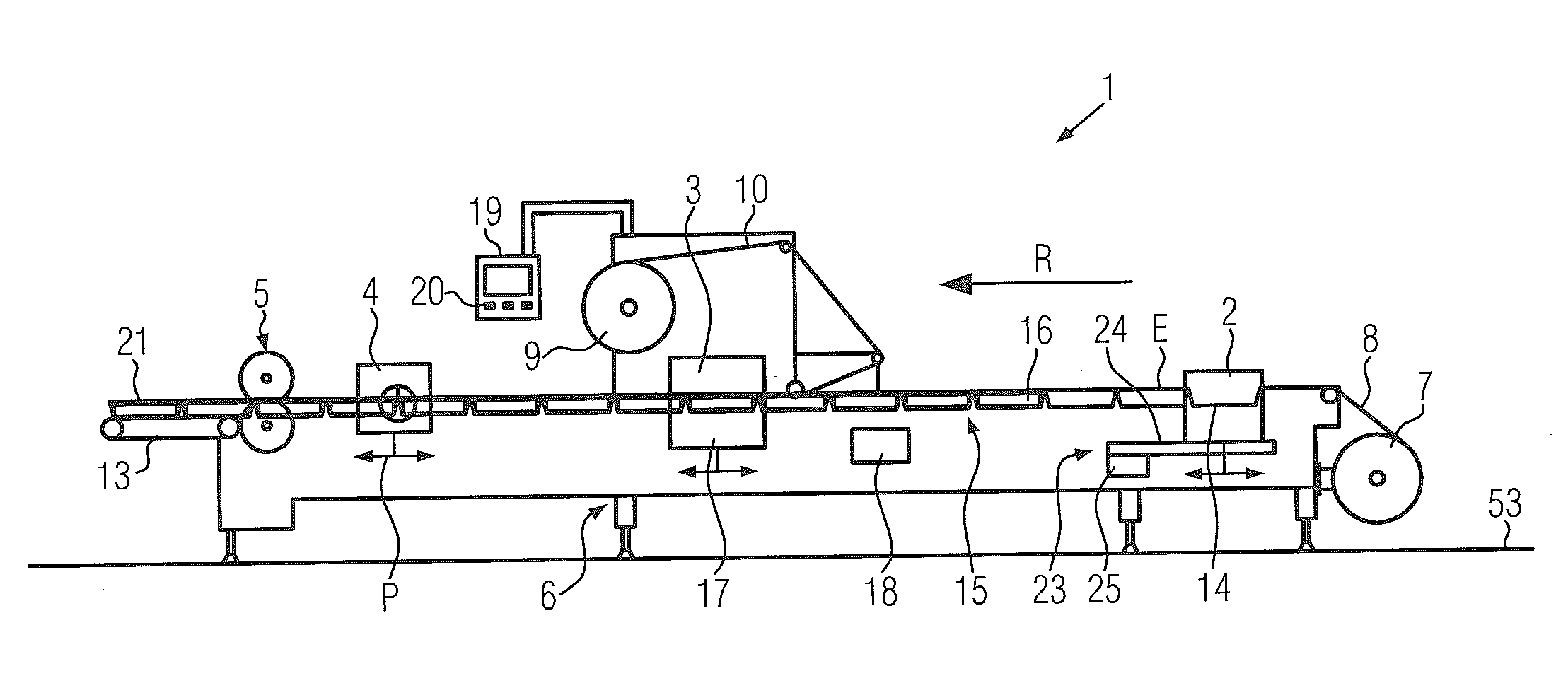
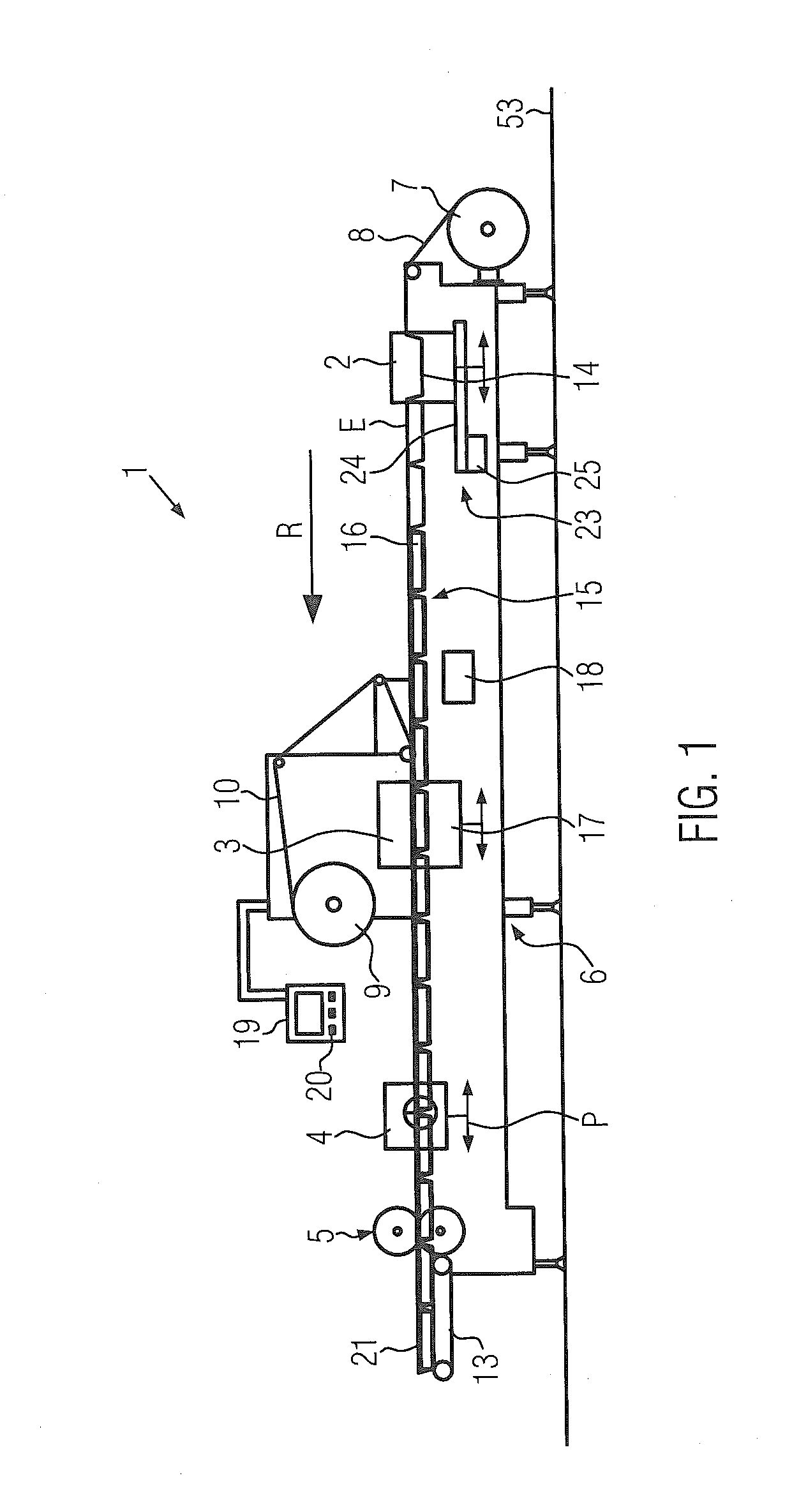
[0029]FIG. 1 shows a schematic view of a packaging machine 1 in the form of a thermoform packaging machine. This thermoform packaging machine 1 comprises a forming station 2, a sealing station 3, a cross cutting unit 4 and a longitudinal cutting unit 5 which are arranged on a machine frame 6 in a working direction R in this sequence. The cross cutting unit 4 according to this embodiment is implemented as a cutting unit according to the present invention, which will be described in more detail hereinbelow.

[0030]On the input side, the machine frame 6 has provided thereon a supply roll 7 from which a first web-shaped packaging material 8 is unwound. In the area of the sealing station 3, a material storage unit 9 is provided, from which a second web-shaped material 10 is unwound as a lidding web. On the output side, a discharge device 13 in the form of a conveyor belt is provided at the packaging machine, with which finished, singulated packages 21 are transported away. Furthermore, the...


PUM

PropertyMeasurementUnit
Distanceaaaaaaaaaa
Transport propertiesaaaaaaaaaa

Abstract

The present invention relates to a work station for a packaging machine, comprising an upper tool and a lower tool arranged below the upper tool. These tools are configured for acting on a packaging web. A lifting unit is able to move the upper tool and/or the lower tool such that, at a specific position, the two tools abut on one another or are only spaced apart at a small distance. According to the present invention, the two tools are adapted to be coupled to one another by a releasable coupling at this position so that they can be removed from the work station in common. The invention also relates to a corresponding method for removing a lower tool from a work station, e.g. for the purpose of tool exchange.

Description

CROSS-REFERENCE TO RELATED APPLICATION[0001]This Application claims priority to German Application Number 102011101053.3 filed May 10, 2011 to Elmar Ehrmann and Helmut Sparakowski entitled “Work Station for a Packaging Machine and Tool Changing Method,” currently pending, the entire disclosure of which is incorporated herein by reference.TECHNICAL FIELD[0002]The present invention relates to a work station for a thermoform packaging machine and to a method of removing a lower tool from a work station.BACKGROUND[0003]Packaging machines for packaging articles to be packed with a packaging web material are known to a sufficient extent. For example, DE 10 2007 013 698 A1 or DE 10 2009 022 545 A1 disclose thermoform machines as a special type of packaging machines. In these thermoform packaging machines, packaging troughs are thermoformed in a bottom film / foil, filled with a product or articles to be packed, and subsequently sealed with a lidding web. After having been sealed, the package...

Claims


Application Information

Patent Timeline
IPC IPC(8): B23Q3/00B23P11/00
CPCB29C33/30B65B9/04B65B59/02Y10T483/17Y10T483/10Y10T483/15B65B59/04B65B59/003Y10T483/1729B21D37/147B29C33/306B29C33/308B29C33/32B29C51/082B30B15/028
Inventor EHRMANN, ELMARSPARAKOWSKI, HELMUT
Owner MULTIVAC SEPP HAGGENMULLER GMBH & CO KG
Why Eureka
Try Eureka