
Alveolar bone regenerative apparatus

Inactive Publication Date: 2012-11-08
TOMINAGA TOSHIHIKO
View PDF2 Cites 2 Cited by
  • Summary
  • Abstract
  • Description
  • Claims
  • Application Information

AI Technical Summary

Benefits of technology

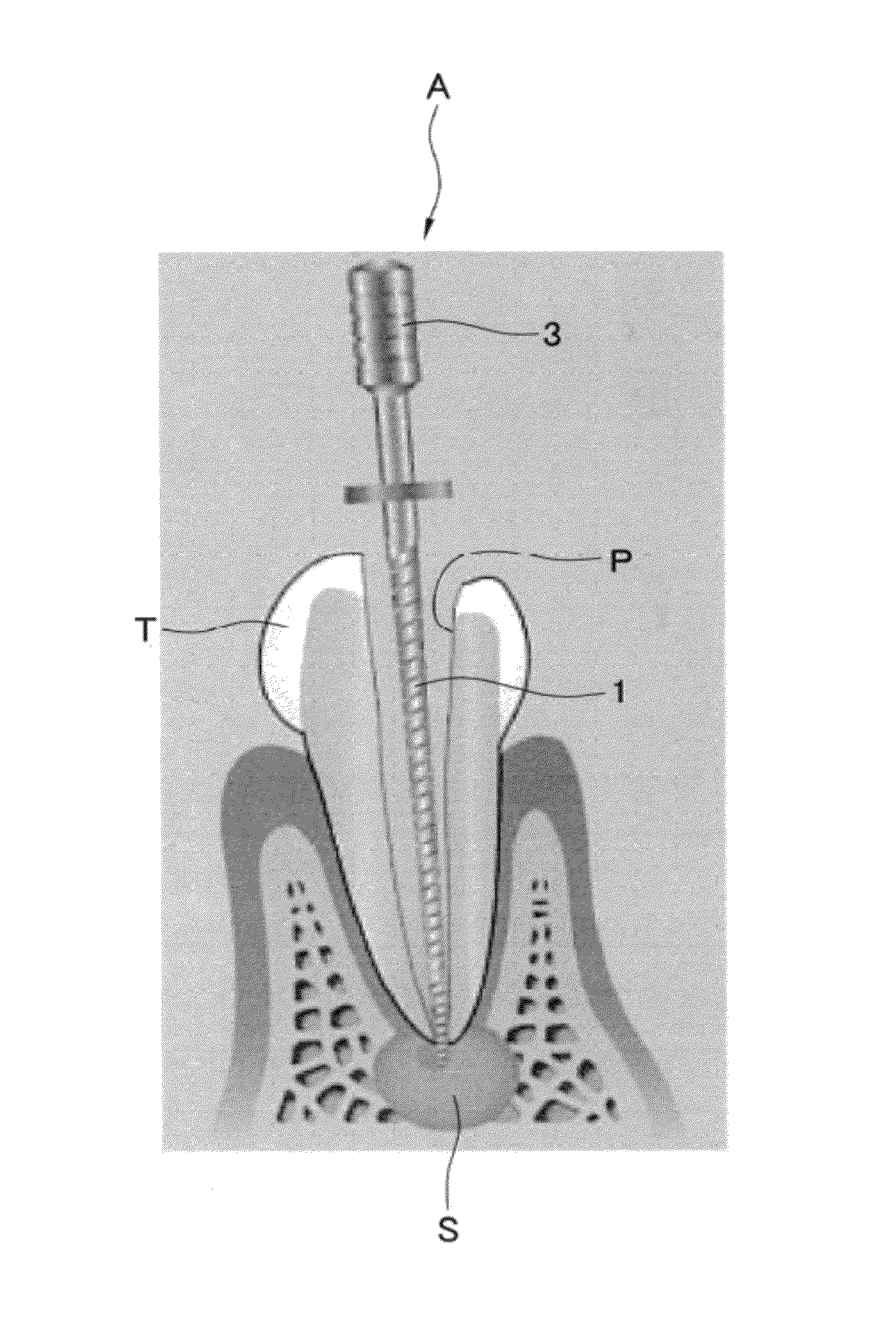
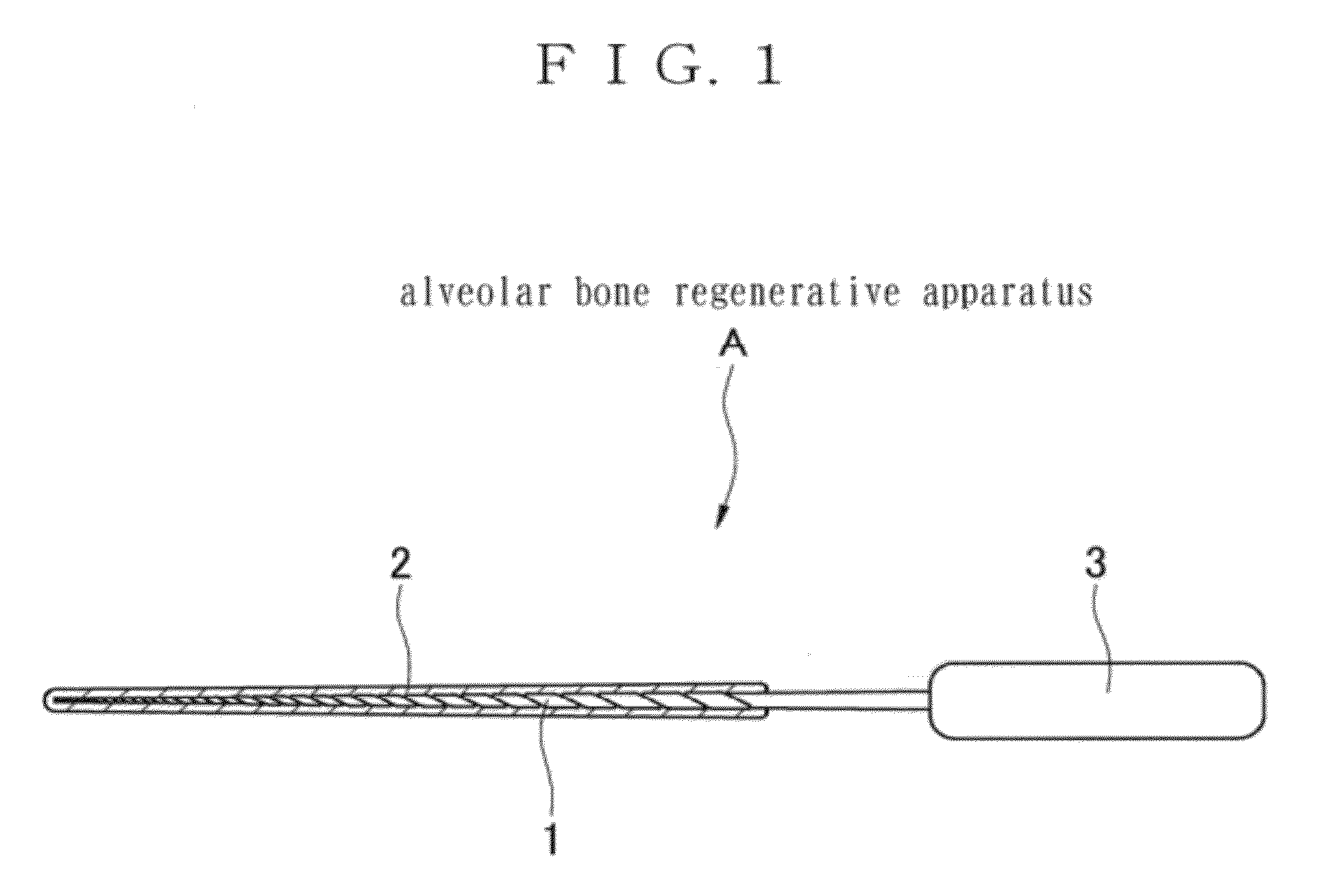
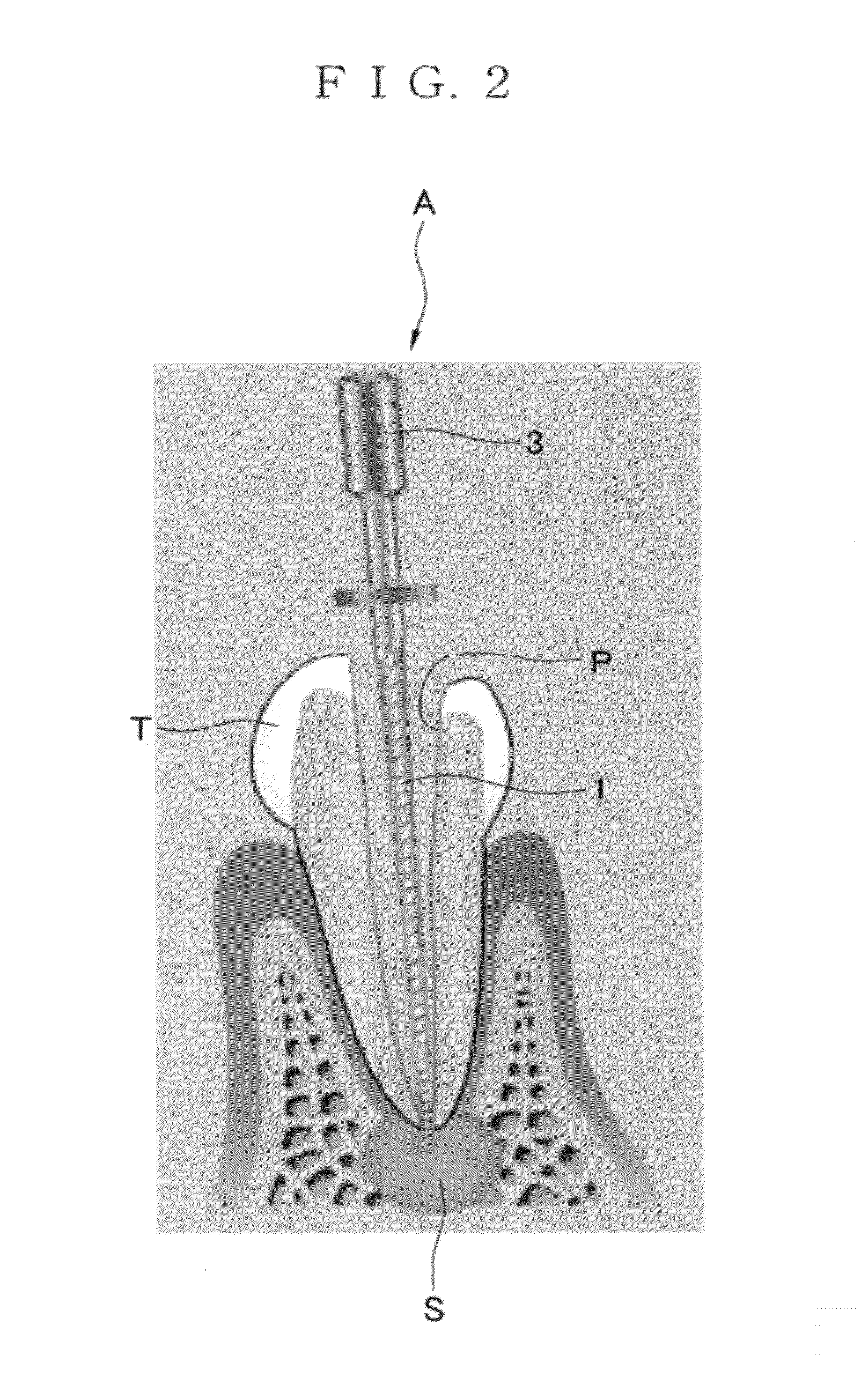
[0015]According to the first feature of the present invention, following effects can be obtained.a) Since the active needle electrode is 0.08 to 0.47 mm in diameter and 25.0 to 41.0 mm long, it can pass through a root canal of a tooth and the tip thereof can reach a periphery of a root. Supplying power to the active needle electrode causes heat generation at a high temperature because of the thin diameter. The high temperature and electric energy can kill bacteria around the root and activate an osteoblast. Thus, killing the bacteria and activating the osteoblast cause a root apex lesion to enter into a healing process, thereby being able to regenerate an alveolar bone.b) A heat treatment can be performed to a different part of the lesion by gradually changing a stripped-off part of the coat of the active needle electrode.c) A lesion tissue can be heat-coagulated without an incision because a current supplied from the electro-surgical unit is a tone burst wave and in between waveforms is discontinuous.
[0016]According to the second feature of the present invention, the active needle electrode can be tightly coated because of the spiral shape, thereby preventing the coat from being unnoticeably stripped off.
[0017]According to the third feature of the present invention, the active needle electrode can be easily inserted into the root canal of the tooth because of the tapered shape with the tip being sharp. Moreover, damages hardly arise because of the base being thick.
[0018]According to the fourth feature of the present invention, the tip of the active needle electrode can easily pass through the root canal of the tooth because of the very sharp tip of 0.08 to 0.15 mm in diameter.

Problems solved by technology

However, once the tooth extraction is performed, the tooth cannot be regenerated again.
According to the conventional technique, a pulp is devitalized only and the root apex lesion cannot be cured.
That is, the bad alveolar bone cannot be regenerated.

Method used


Image

  • Alveolar bone regenerative apparatus
  • Alveolar bone regenerative apparatus
  • Alveolar bone regenerative apparatus

Examples


example

[0055]An effect of bone regeneration is described based on a treatment example for which the alveolar bone regenerative apparatus of the present invention is used.

(Treatment Condition)

[0056]The alveolar bone regenerative unit A of the present invention is used for treatment to a patient who has a tooth with an intractable root apex lesion whose clinical presentation cannot be remitted by an ordinary endodontic treatment, and a tooth that cannot bear bite force because absorption of an alveolar bone is serious.

(Results)

[0057]The table of FIG. 5 shows results of the treatment.

[0058]Initials of 42 participants in clinical trial are written in a name column of the table. “Lesion” indicates a cavity caused by melting a bone around a root and is classified according to a table below. Additionally, reference character M indicates the number of months elapsed in the table of FIG. 5. Each irradiation is performed with 500 kHz×1 sec and the number of shots is derived from dividing a greatest ...


PUM


Abstract

Provided is an alveolar bone regenerative unit and an alveolar bone regenerative apparatus capable of regeneration treatment for an alveolar bone by sterilizing a periodontium and activating an osteoblast. The alveolar bone regenerative unit includes an active needle electrode of a metal electrode generating heat by power supply and a handle attached to a base of the active needle electrode. The active needle electrode is 25.0 to 41.0 mm long and 0.08 to 0.47 mm in diameter, on which a strippable coat is formed with silicon resin. Supplying power to the active needle electrode causes heat generation at a high temperature because of the thin diameter. The high temperature and electric energy can kill bacteria around a root, thereby being able to activate an osteoblast and regenerate an alveolar bone.

Description

BACKGROUND OF THE INVENTION[0001]1. Field of the Invention[0002]The present invention relates to an alveolar bone regenerative apparatus and, more particularly, to a treatment apparatus for regenerating an absorbed alveolar bone to be healthy.[0003]2. Description of the Related Art[0004]In a human tooth structure, a root of the tooth is surrounded and supported by an alveolar bone, and connected to a jawbone. The tooth is also surrounded by a gingiva at an upper side of the alveolar bone. When the tooth is decayed and bacteria in a nerve of the tooth reach a periphery of the root through a root canal, etiological agents are released to the alveolar bone for melting and absorbing the bone. This is called a root apex lesion.[0005]As the alveolar bone is absorbed due to the root apex lesion, the tooth is not supported by the alveolar bone and becomes loose. According to the present treatment, tooth extraction is preformed if the alveolar bone is absorbed up to two thirds of the root or...

Claims


Application Information

Patent Timeline
IPC IPC(8): A61N1/00
CPCA61B18/1477A61B2018/00321A61C8/0007A61C5/02A61B2018/00589A61C5/40
Inventor TOMINAGA, TOSHIHIKO
Owner TOMINAGA TOSHIHIKO
Learn More