
Antenna mount

a technology for antennas and mounting brackets, applied in the direction of antennas, antenna details, polarised antenna unit combinations, etc., to achieve the effect of sufficient rigidity

Active Publication Date: 2012-11-08
KIRKHAM JEFFREY B
View PDF7 Cites 35 Cited by
  • Summary
  • Abstract
  • Description
  • Claims
  • Application Information

AI Technical Summary

Problems solved by technology

Such a user may be operating in a generally hostile environment (e.g., a combat zone).

Method used


Image

  • Antenna mount
  • Antenna mount
  • Antenna mount

Examples


Embodiment Construction

[0018]I. Introduction

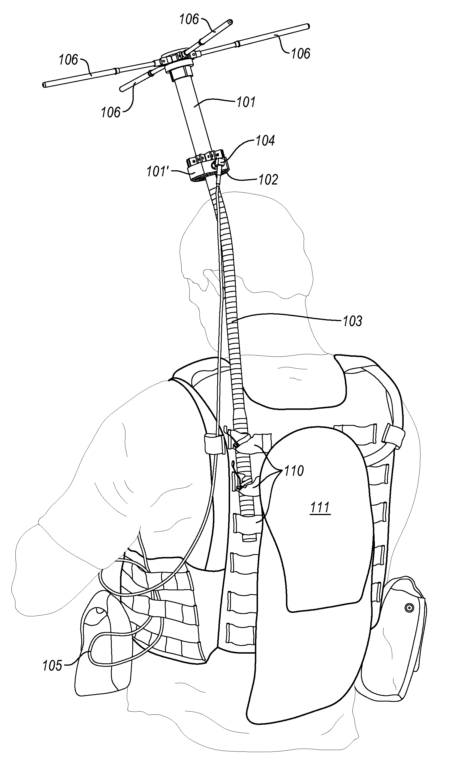
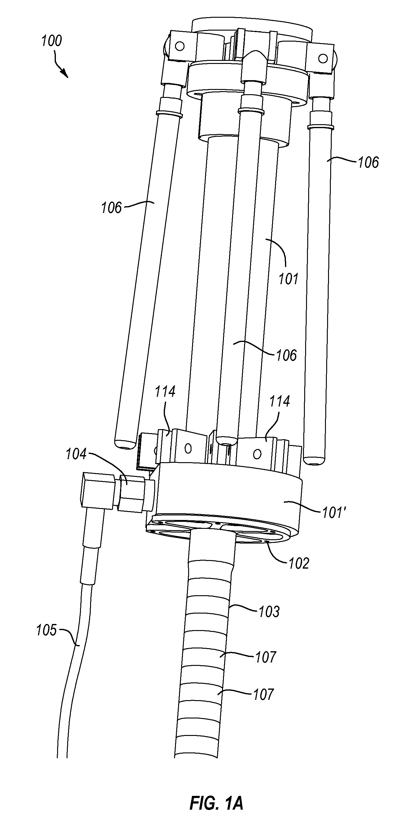
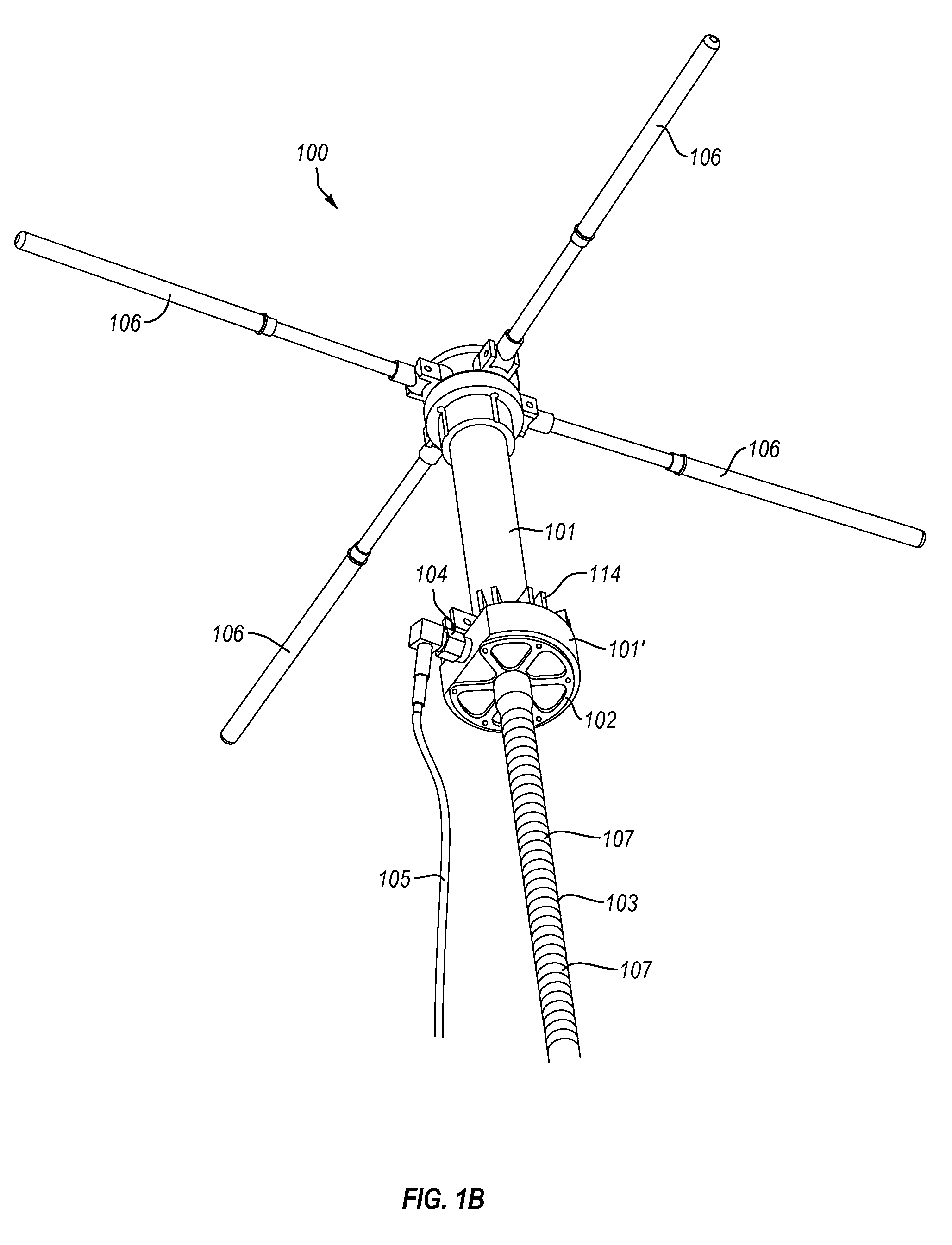
[0019]The present invention is directed to a pedestrian transportable antenna system configured to be easily and quickly mountable to a back of a user (e.g., through mounting the system to a vest or flak jacket). The antenna system includes an antenna mount, a bendable rigid rod attached to the antenna mount, and an antenna attached to the opposite face of the antenna mount. The antenna includes a connection for an antenna cable, and one or more selectively extendable and retractable antenna members. The bendable rigid rod is sufficiently rigid to support the weight of the antenna at a specified orientation (e.g., oriented generally vertically). At the same time, the bendable rigid rod is bendable to a different specified orientation when sufficient force is applied (e.g., laterally) to adjust the bendable rigid rod. For example, the bendable rigid rod may be bent downward, over the user's shoulder to allow the user to easily step into a vehicle.

[0020]II. Exempl...


PUM


Abstract

Pedestrian transportable antenna systems can include an antenna mount and an antenna for satellite based or other communication mounted on a top face of the antenna mount. A bottom face of the antenna mount may be attached to a bendable rigid rod that is sufficiently rigid to provide support for the mounted antenna such that a user can walk around with the antenna deployed while the bendable rigid rod of the antenna system is mounted to the user's back (e.g., mounting into a back portion of a vest or flak jacket). The bendable rigid rod is sufficiently rigid to support the antenna without allowing the rod to “flop” over under the load of the antenna. At the same time, the rod is sufficiently bendable so as to permit the system to be drawn closer into a user's body when the antenna is not deployed (e.g., while stepping into a vehicle).

Description

CROSS REFERENCE TO RELATED APPLICATIONS[0001]This application claims the benefit of U.S. Provisional Patent Application No. 61 / 483,565, filed May 6, 2011 entitled ANTENNA MOUNT, the disclosure of which is incorporated herein in its entirety.BACKGROUND[0002]1. Field of the Invention[0003]The present invention relates to antenna mounts. In particular, the invention relates to a portable antenna mount for use by an individual on foot.[0004]2. Background and Relevant Art[0005]While antenna systems are used generally in order to provide for improved transmittal and / or reception of radio or other communication signals, a need exists for a system that provides for portability, particularly in the context of a user that may be on foot (i.e., pedestrian). Such a user may be operating in a generally hostile environment (e.g., a combat zone). As such, there continues to be a general need for improved antenna mounts that can facilitate the overall convenience, speed and / or stealth at which the ...

Claims


Application Information

Patent Timeline
Patent Type & Authority Applications(United States)
IPC IPC(8): H01Q1/12
CPCH01Q1/084H01Q21/26H01Q1/273H01Q1/1235
Inventor KIRKHAM, JEFFREY B.
Owner KIRKHAM JEFFREY B
Learn More