Method And System For Compensating For Antenna Pulling

a technology of antenna pulling and compensating method, which is applied in the direction of resonant long antennas, transmission, electrical equipment, etc., can solve the problems of limited wide-spread deployment of multi-antenna systems in wireless communications, particularly in wireless handheld devices, and increase the size, complexity, power consumption, and the effect of affecting the operation of wireless handheld devices

Inactive Publication Date: 2008-04-03
AVAGO TECH INT SALES PTE LTD
View PDF15 Cites 13 Cited by
  • Summary
  • Abstract
  • Description
  • Claims
  • Application Information

AI Technical Summary

Benefits of technology

[0032]A system and method for compensating for antenna pulling, substantially as shown in and / or described in connection with at least one of the figures, as set forth more completely in the claims.

Problems solved by technology

However, the widespread deployment of multi-antenna systems in wireless communications, particularly in wireless handheld devices, has been limited by the increased cost that results from the increased size, complexity, and power consumption.
Furthermore, operation of the wireless handheld device may be significantly affected by the operating conditions of the wireless device antenna.
In such instances, antenna pulling may result, which causes degradation of performance of the wireless handheld device.

Method used


Image

  • Method And System For Compensating For Antenna Pulling
  • Method And System For Compensating For Antenna Pulling
  • Method And System For Compensating For Antenna Pulling

Examples


Embodiment Construction

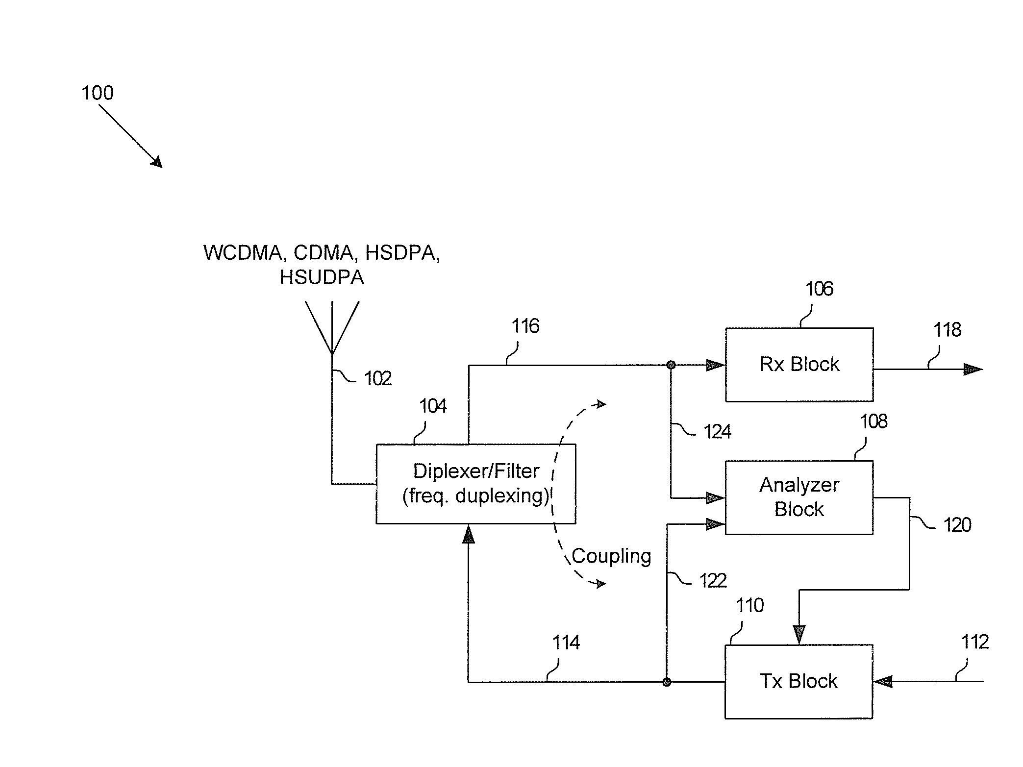
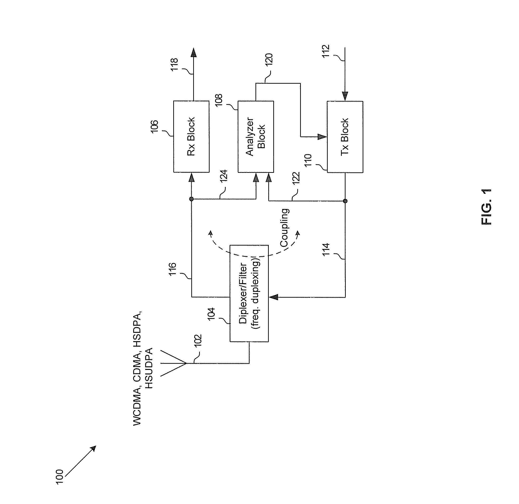
[0040]Certain embodiments of the invention may be found in a method and system for compensating for antenna pulling and may comprise sampling a portion of a transmitted wireless signal which gets coupled to receiver circuitry in a receive chain. The wireless signal may be transmitted via an antenna. The DC level corresponding to the sampled portion of the transmitted wireless signal may be measured. The transmit power corresponding to the transmitted wireless signal may be adjusted based on the measured DC level. The antenna may comprise a mobile antenna. The sampled portion of the transmitted wireless signal may be buffered. The buffered portion of the transmitted wireless signal may be multiplied with the transmitted wireless signal to generate a multiplied signal, and the DC level may be measured using the multiplied signal. A control signal may be generated based on the measured DC level and, for example, a look-up table. The look-up table may comprise a user-customizable look-u...


PUM


Abstract

Methods and systems for wireless communication are disclosed herein and may include sampling a portion of a transmitted wireless signal which gets coupled to receiver circuitry in a receive chain during transmission via an antenna. The DC level corresponding to the sampled portion of the transmitted wireless signal may be measured. The transmit power corresponding to the transmitted wireless signal may be adjusted based on the measured DC level. The antenna may include a mobile antenna, which may be coupled to a wireless terminal. The sampled portion of the transmitted wireless signal may be buffered. The buffered portion of the transmitted wireless signal may be multiplied with the transmitted wireless signal to generate a multiplied signal, and the DC level may be measured using the multiplied signal. A control signal may be generated based on the measured DC level and, for example, a look-up table.

Description

CROSS-REFERENCE TO RELATED APPLICATIONS / INCORPORATION BY REFERENCE[0001]This application makes reference to:[0002]U.S. application Ser. No. ______ (Attorney Docket No. 17783US01), filed on even date herewith;[0003]U.S. application Ser. No. ______ (Attorney Docket No. 17784US01), filed on even date herewith;[0004]U.S. application Ser. No. ______ (Attorney Docket No. 17785US01), filed on even date herewith;[0005]U.S. application Ser. No. ______ (Attorney Docket No. 17786US01), filed on even date herewith;[0006]U.S. application Ser. No. ______ (Attorney Docket No. 17787US01), filed on even date herewith;[0007]U.S. application Ser. No. ______ (Attorney Docket No. 17788US01), filed on even date herewith;[0008]U.S. application Ser. No. ______ (Attorney Docket No. 17789US01), filed on even date herewith;[0009]U.S. application Ser. No. ______ (Attorney Docket No. 17790US01), filed on even date herewith;[0010]U.S. application Ser. No. ______ (Attorney Docket No. 17791US01), filed on even dat...

Claims


Application Information

Patent Timeline
Patent Type & Authority Applications(United States)
IPC IPC(8): H04B1/18
CPCH04B1/04
Inventor ROFOUGARAN, AHMADREZA
Owner AVAGO TECH INT SALES PTE LTD
Why Eureka
Try Eureka