Eureka AIR delivers breakthrough ideas for toughest innovation challenges, trusted by R&D personnel around the world.

Fluorescence detecting optical system and multi-channel fluorescence detection apparatus including the same

a fluorescence detection and optical system technology, applied in the direction of fluorescence/phosphorescence, luminescent dosimeters, optical radiation measurement, etc., can solve the problems of increasing the volume and manufacturing cost of the fluorescence detection optical system, and the difficulty of uniformly and accurately detecting fluorescen

Active Publication Date: 2012-11-08
SAMSUNG ELECTRONICS CO LTD
View PDF2 Cites 37 Cited by
  • Summary
  • Abstract
  • Description
  • Claims
  • Application Information

AI Technical Summary

Benefits of technology

[0008]Provided are fluorescence detection optical systems that maintain a focal position through an automatic focusing function so

Problems solved by technology

If such controls are not precise, focal points formed between chambers in the microfluidic device are formed differently, and thus it is difficult to uniformly and accurately detect fluorescence.
Also, if the microfluidic device is attached to or detached from the fluorescence detection optical system, the fluorescence detection optical system needs to maintain its accuracy, and thus a mechanism for attaching or detaching the microfluidic device needs to be precise and thus is complicated, which increases a volume and manufacturing cost of the fluorescence detection optical system.

Method used


Image

  • Fluorescence detecting optical system and multi-channel fluorescence detection apparatus including the same
  • Fluorescence detecting optical system and multi-channel fluorescence detection apparatus including the same
  • Fluorescence detecting optical system and multi-channel fluorescence detection apparatus including the same

Examples


Embodiment Construction

[0047]Reference will now be made in detail to embodiments, examples of which are illustrated in the accompanying drawings, wherein like reference numerals refer to like elements throughout. In this regard, the embodiments may have different forms and should not be construed as being limited to the descriptions set forth herein. Accordingly, the embodiments are merely described below, by referring to the figures, to explain aspects of the present description.

[0048]It will be understood that, although the terms first, second, third, etc., may be used herein to describe various elements, components, regions, layers and / or sections, these elements, components, regions, layers and / or sections should not be limited by these terms. These terms are only used to distinguish one element, component, region, layer or section from another region, layer or section. Thus, a first element, component, region, layer or section discussed below could be termed a second element, component, region, layer...


PUM


Abstract

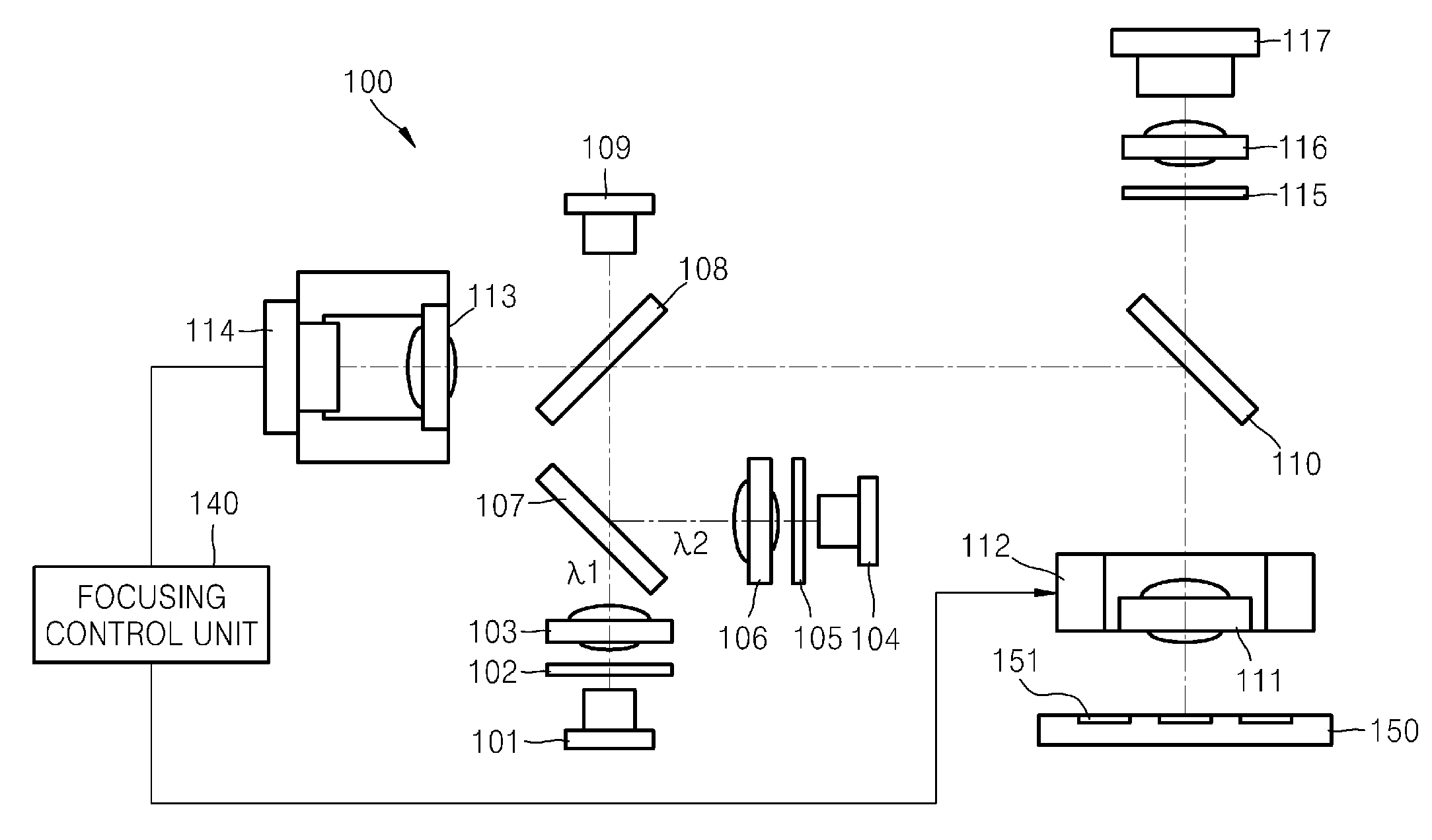
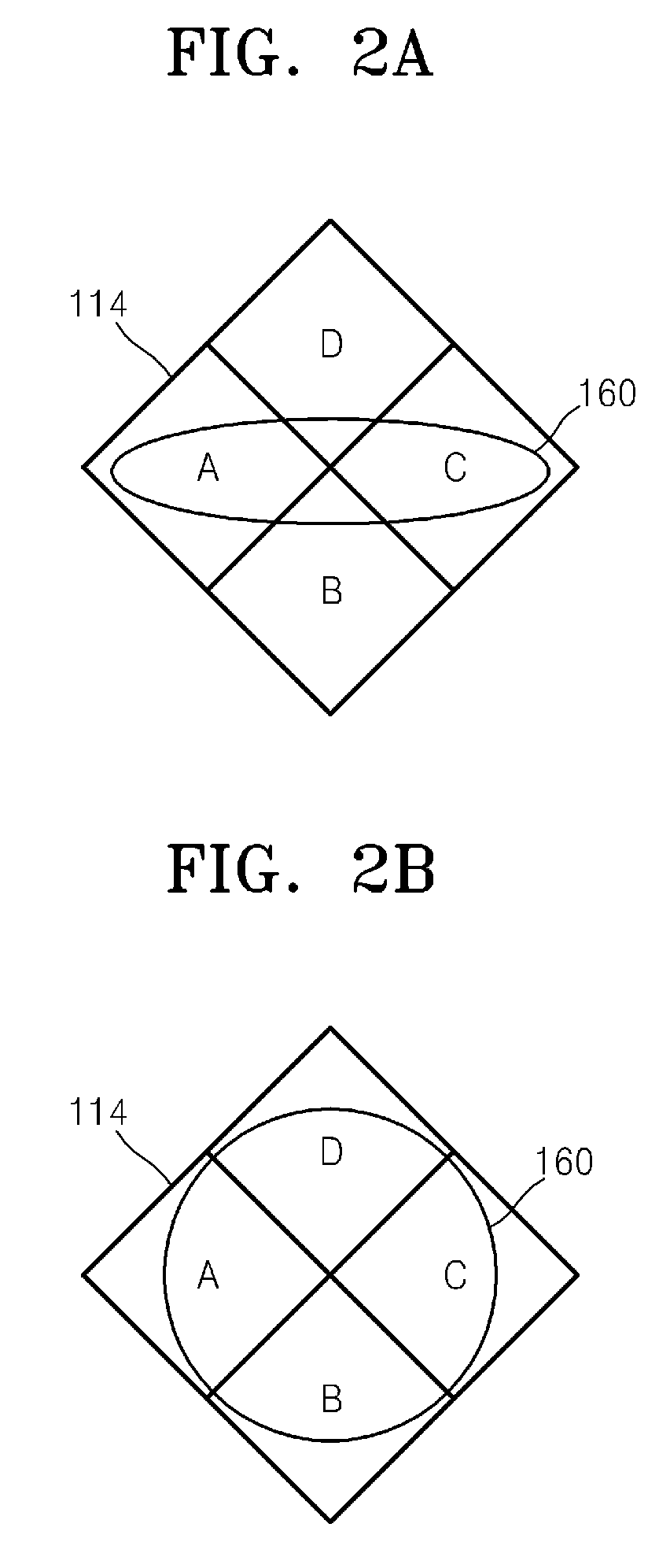
A fluorescence detection optical system detects fluorescence beams with two or more different wavelengths and maintains a focal position through an automatic focusing function. A multi-channel fluorescence detection apparatus includes the fluorescence detection optical system. The fluorescence detection optical system includes an automatic focusing unit which receives light reflected off a microfluidic device and determines a focal point by using an astigmatic method or a knife edge method, and an actuator which adjusts a position of an objective lens according to control of the automatic focusing unit. In addition, the fluorescence detection optical system may include a plurality of dual band pass filters, dichroic devices, etc., which provide light beams emitted from at least two light sources and transfer fluorescence generated from the microfluidic device to a photodetector.

Description

CROSS-REFERENCE TO RELATED APPLICATIONS[0001]This application claims priority to Korean Patent Application No. 10-2011-0041994, filed on May 3, 2011, and all the benefits accruing therefrom under 35 U.S.C. §119, the disclosure of which is incorporated herein in its entirety by reference.BACKGROUND[0002]1. Field[0003]Provided is a fluorescence detection optical system and a multi-channel fluorescence detection apparatus including the same, and more particularly, a fluorescence detection optical system for detecting fluorescence beams with two or more different wavelengths, and for maintaining a constant focal point through an automatic focusing function, and a multi-channel fluorescence detection apparatus including the fluorescence detection optical system.[0004]2. Description of the Related Art[0005]In accordance with the advent of point of care diagnosis, various medical experiments such as gene analysis, external diagnosis, and nucleic acid sequence analysis, for example, have be...

Claims


Application Information

Patent Timeline
IPC IPC(8): G01N21/64
CPCG01J3/4406G01N21/05G01N21/645G01N2021/6419G01N2021/6421G01N2021/0346G01N2201/0635G01J3/0237G01J3/0208G01J3/0229G01N2021/6478
Inventor KIM, KYUNG-HOKIM, JOON-HONAMKOONG, KAKCHUNG, WON-SEOK
Owner SAMSUNG ELECTRONICS CO LTD
Why Eureka
Eureka Blog
Learn More