
Coin Sorting Plate with Recessed Coin Slots

a coin slot and coin sorting technology, applied in coin/paper handlers, coin dispensers, instruments, etc., to achieve the effect of reducing the risk of jamming

Active Publication Date: 2012-11-01
GCCM
View PDF13 Cites 6 Cited by
  • Summary
  • Abstract
  • Description
  • Claims
  • Application Information

AI Technical Summary

Benefits of technology

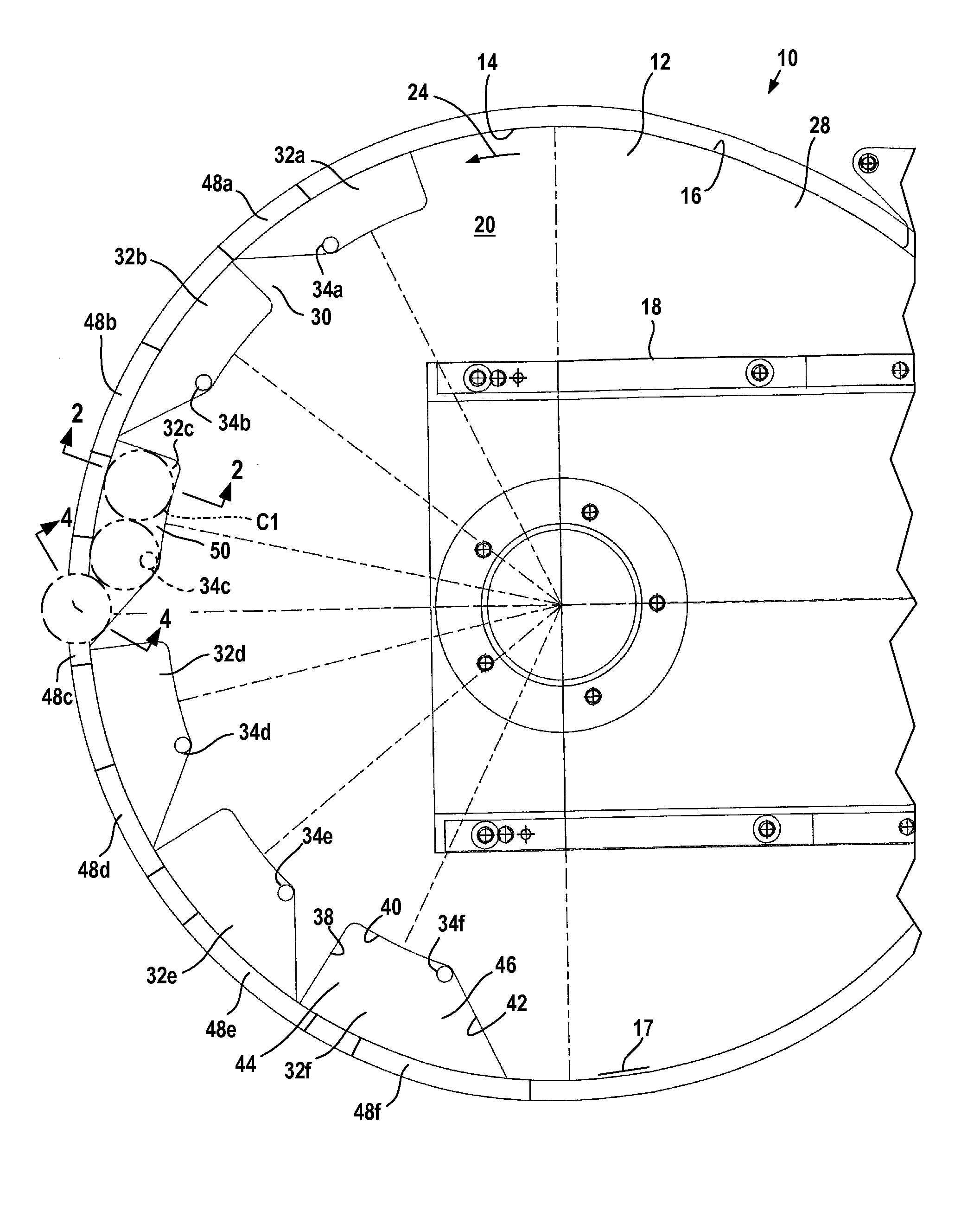
[0006]The invention is an improved coin sorting plate for a coin sorting machine that reduces the risk of jamming when operated at high speed.
[0012]Using the coin receiving recesses of the present invention has a number of advantages. Coins only need to drop a relatively short distance into a recess, and so the risk of jamming is substantially reduced at higher operating speeds. The downstream wall affirmatively directs coins in the recess off the coin sorting plate, enabling the coins to move at high speeds off the coin sorting plate. The downstream wall can direct coins either in the radially inner or radially outer direction off the coin sorting plate, enabling a more compact overall assembly or providing more space for coin receiving bags and the like. Sensing individual coins in the recesses is more reliable and can easily individually count even two touching coins.

Problems solved by technology

A problem with a conventional coin sorting plate is that coins may not fall through an opening before striking the downstream wall defining the coin opening.
This is particularly a problem when attempting to run the coin sorting machine at a relatively high speed.

Method used


Image

  • Coin Sorting Plate with Recessed Coin Slots
  • Coin Sorting Plate with Recessed Coin Slots
  • Coin Sorting Plate with Recessed Coin Slots

Examples


second embodiment

[0037]FIG. 6 illustrates a portion of a second embodiment coin sorting plate 112 that has a radially-inner peripheral wall 114 extending around an inner periphery of the sorting plate 112. Coins are driven in a downstream direction 124 along the inner wall 114 by the upper disk for sorting. The coin sorting plate 112 has a number of coin recesses 132 (to simplify the drawing, only one coin recess is shown) that each carry a coin sensor 134.

[0038]Each coin recess 132 extends along the inner wall 114 and has a radial width sized to closely receive a coin of the diameter associated with the coin recess in the recess as previously described. In this embodiment the downstream wall 142 extends from the inner wall 114 and directs the coin in the recess radially outwardly off the outer periphery of the sorting plate 112. The inner wall 114 has no openings along the coin recesses 132, instead the downstream wall 142 cooperates with a second parallel wall 142′ to define a coin chute 144 that ...

third embodiment

[0040]FIG. 7 illustrates a portion of a third embodiment coin sorting plate 212 that has a radially-inner peripheral wall 214 extending around an inner periphery of the sorting plate 212. Coins are driven in a downstream direction 124 along the inner wall 214 by the upper disk for sorting. The coin sorting plate 212 has a number of coin recesses 232 (to simplify the drawing, only one coin recess is shown) similar to the coin recesses 32 that each carry a coin sensor 134.

[0041]Each coin recess 132 extends along the inner wall 114 and has a radial width sized to closely receive a coin of the diameter associated with the coin recess in the recess as previously described. In this embodiment the downstream wall 242 extends from the outer radial wall 240 towards the inner wall 214 and directs the coin in the recess through an opening 242 in the inner wall 214.

[0042]The coin sorting plates 12, 112, 212 can also be configured to verify coins rather than sort coins. A coin sorting plate 12, ...


PUM


Abstract

A coin sorting plate for receiving and sorting a stream of coins by the diameter and hence the denomination of the coin has a number of coin recesses that extend along the path of the coin stream. Each coin recess is sized to receive a respective coin diameter. The coin recesses are arranged with the recess openings increasing in size in the downstream direction to progressively remove coins in order of increasing diameter. Each coin recess is bounded by a downstream wall that forces a coin in the recess to move off a peripheral edge of the coin sorting plate for collection or other processing.

Description

FIELD OF THE INVENTION[0001]The invention relates generally to the field of coin processing machines that sort or verify coins based on the diameter of the coins, and in particular the invention relates to a coin sorting plate for a coin processing machine.BACKGROUND OF THE INVENTION[0002]A conventional coin processing machine as disclosed in my U.S. Pat. No. 7,243,774 includes a circular sorting plate. A single-layer stream of coins are introduced on an upper surface of the sorting plate, and are urged by centrifugal force against a peripheral wall extending along the outside of the plate. A rotating disk above the sorting plate has fingers that extend down and engage the coins. The fingers urge the coins circumferentially in a downstream direction around the disk, with the radially outer edges of the coins bearing against the wall.[0003]The sorting plate has circumferentially-spaced openings adjacent the wall. Each opening extends through the thickness of the sorting plate and is ...

Claims


Application Information

Patent Timeline
IPC IPC(8): G07D3/00
CPCG07D3/128
Inventor STRING, GREGORY F.
Owner GCCM
Learn More