
Rapidly deployable buggies for a stage system

a stage system and buggie technology, applied in the field of stage systems, can solve the problems of inability to provide the equipment necessary for the event, complex, custom-built performance equipment is impractical, amateur environment provided by low-end systems is unacceptable to the performers and/or promoters of the event, etc., and achieve the effect of reducing costs

Inactive Publication Date: 2012-11-01
HITECH STAGES
View PDF0 Cites 21 Cited by
  • Summary
  • Abstract
  • Description
  • Claims
  • Application Information

AI Technical Summary

Benefits of technology

[0007]The present disclosure describes buggies for a rapidly deployable, fully integrated staging system that provides a high-end, professional performance environment at substantially reduced costs compared to conventional systems.
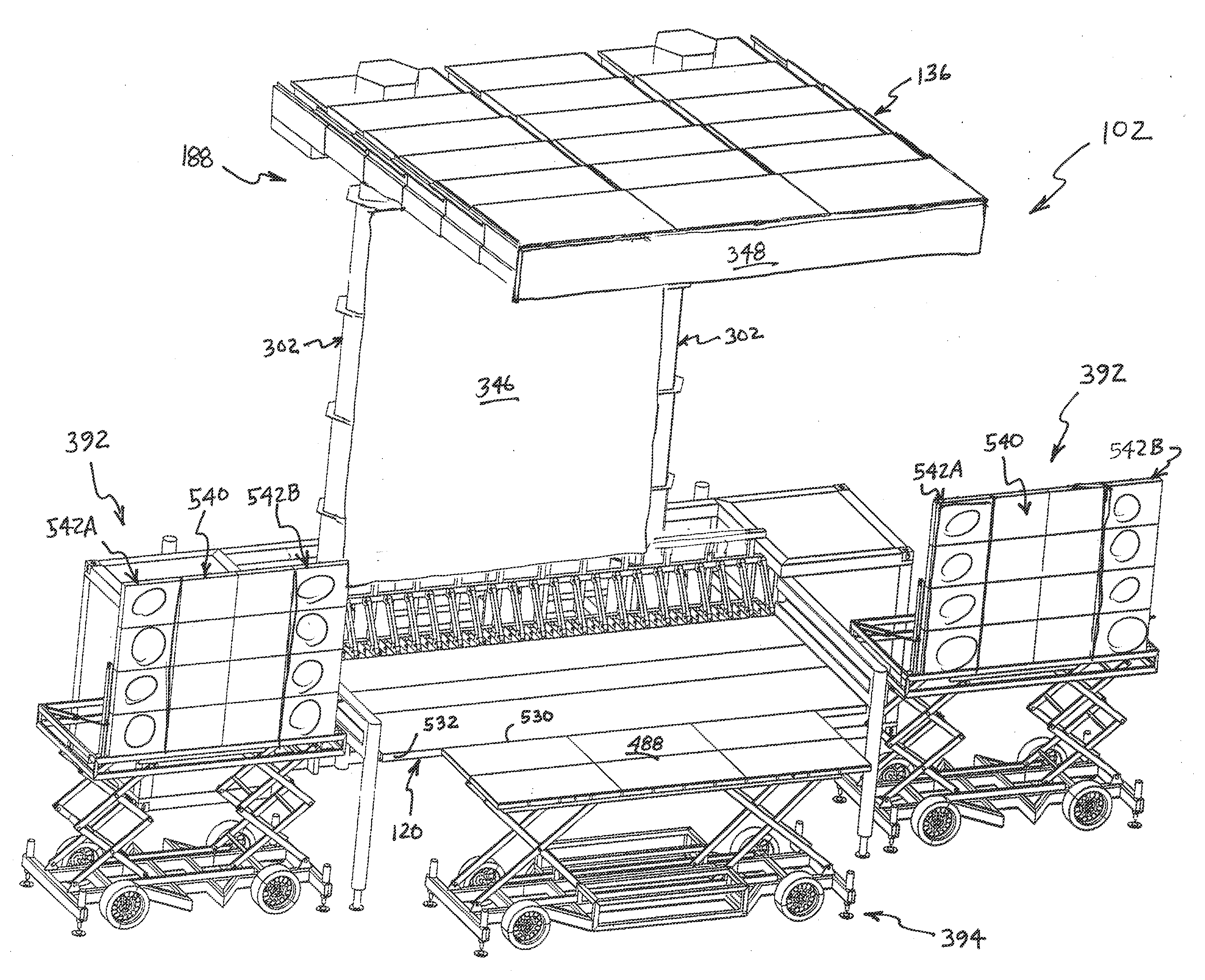
[0008]One embodiment of the present disclosure provides a buggy for enhancing a performance, including a frame, an engine mounted to the frame, a pair of wheel assemblies mounted to the frame, at least one scissor lift mounted to the frame, an upper frame mounted to the at least one scissor lift and configured to be moved by the at least one scissor lift between a stowed position and an in-use position, the upper frame supporting one of a platform and a video display, and a receiver / controller mounted to the frame and coupled to an actuator powered by the engine for operating the engine and the scissor lift. In this embodiment, the receiver / controller is configured to respond to receipt of signals from a remote control by activating the engine, causing the wheel assemblies to move the buggy to a desired location, and activating the at least one scissor lift to raise and lower the upper frame between the stowed position and the in-use position.

Problems solved by technology

Often, the venues for the performance events do not provide the equipment necessary for the event (i.e., the stages, lighting and audio / video equipment—collectively, “performance equipment”), particularly if the venue is outside.
Elaborate, custom-built performance equipment is impractical and the amateur environment provided by low-end systems is unacceptable to the performers and / or promoters of the event.
The convertible trailer systems typically provide a low-impact, “back of a trailer” environment that is unsuitable for many performance events.
This requires substantial set-up and tear-down time and logistics challenges in making sure the equipment is delivered and removed according to the performance schedule.
While these systems may avoid the “back of a trailer” look and feel, they typically also require substantial set-up and tear-down time and auxiliary power, audio, and video equipment.
Additionally, cranes, forklifts and other equipment are typically necessary to unload and configure the components of such systems, adding to the cost of the systems and complicating the scheduling for setup and tear-down.
The logistics and deployment time associated with these conventional mid-market staging solutions essentially preclude their use for a tour including back-to-back performances at different venues.
In many cases it is simply not possible tear-down the performance equipment after a performance, transport it to the next venue, and setup the equipment in time for a performance the next evening.
Of course, this added cost significantly impacts the overall profitability of the tour.

Method used


Image

  • Rapidly deployable buggies for a stage system
  • Rapidly deployable buggies for a stage system
  • Rapidly deployable buggies for a stage system

Examples


Embodiment Construction

[0026]The embodiments of the present teachings described below are not intended to be exhaustive or to limit the teachings to the precise forms disclosed in the following detailed description. Rather, the embodiments are chosen and described so that others skilled in the art may appreciate and understand the principles and practices of the present teachings.

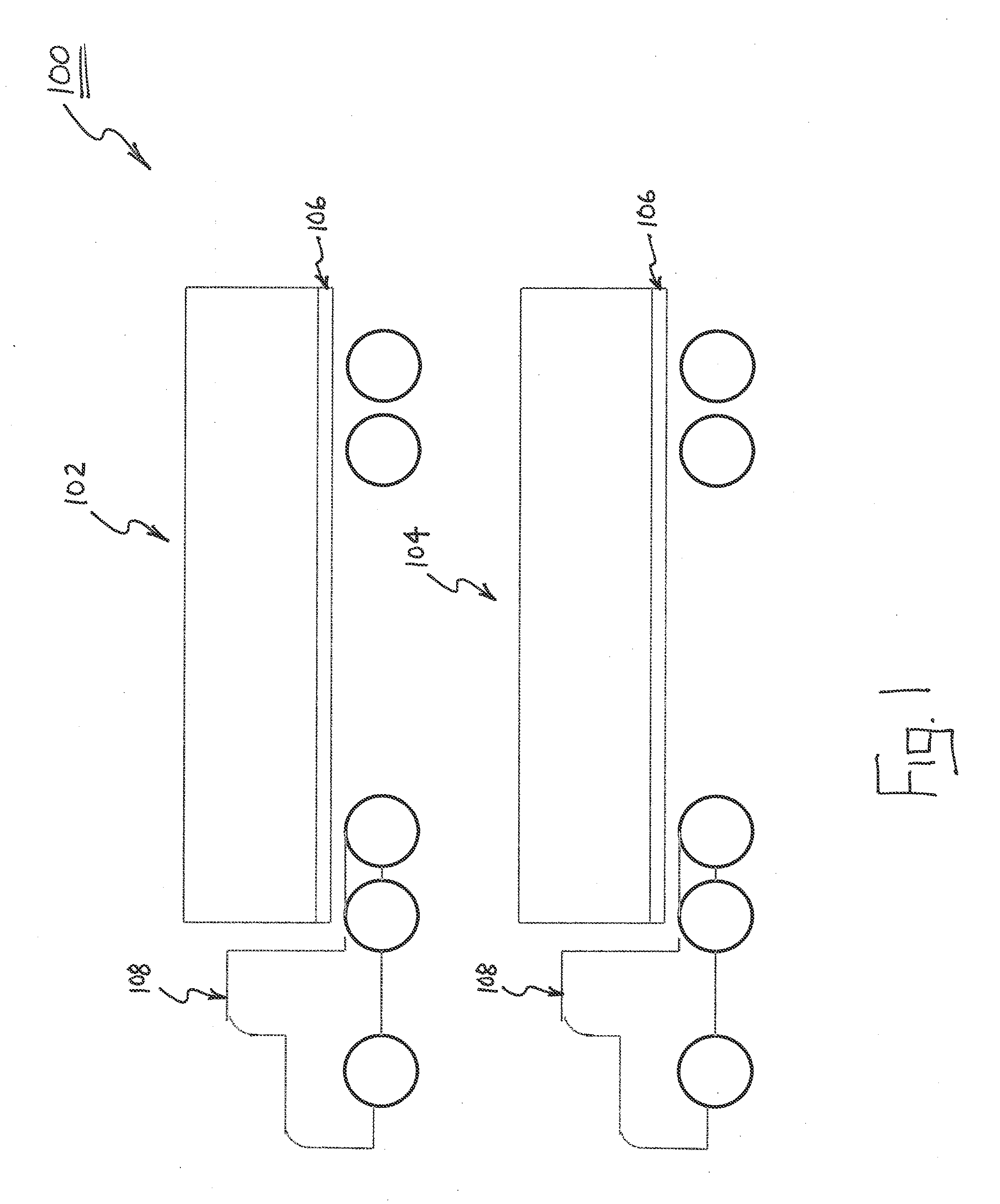
[0027]As shown generally in FIG. 1, system 100 includes a primary stage unit 102 and a secondary stage unit 104. Both units are moved from venue to venue on trailers 106 of standard semi-trucks 108. As is described in detail below, the contents of stage units 102, 104 are unloadable without use of moving equipment such as cranes or forklifts, and are movable into their desired locations using remote controls. Additionally, the contents include all of the lighting and audio / video equipment necessary to provide a high-end, high-impact, professional environment for a performance event. In one embodiment, all of these components may ...


PUM


Abstract

The present disclosure provides a buggy for enhancing a performance, including a frame, an engine, a pair of wheel assemblies, at least one scissor lift, an upper frame mounted to the at least one scissor lift and configured to be moved by the at least one scissor lift between a stowed position and an in-use position, the upper frame supporting one of a platform and a video display, and a receiver / controller mounted to the frame and coupled to an actuator powered by the engine for operating the engine and the scissor lift. The receiver / controller is configured to respond to receipt of signals from a remote control by activating the engine, causing the wheel assemblies to move the buggy to a desired location, and activating the at least one scissor lift to raise and lower the upper frame between the stowed position and the in-use position.

Description

RELATED APPLICATIONS[0001]This application is related to the subject matter of co-filed patent applications entitled RAPIDLY DEPLOYABLE STAGE SYSTEM, docket HTS-P0001, and RAPIDLY DEPLOYABLE PRIMARY STAGE UNIT, docket HTS-P0002, the entire disclosures of which are hereby expressly incorporated herein by reference.FIELD OF THE DISCLOSURE[0002]The present disclosure relates to stage systems that can be moved from one location to another, and more particularly to buggies for a rapidly deployable, fully integrated staging system that provides a high-end, professional performance environment at substantially reduced costs compared to conventional systems.BACKGROUND OF THE DISCLOSURE[0003]Many events such as concerts, speaking engagements, product promotions, fashions shows and the like (collectively, “performance events”) are provided at a variety of different locations over the course of a “tour,” but occur only once at any particular location and last for just a few hours. Often, the v...

Claims


Application Information

Patent Timeline
IPC IPC(8): B60P3/025B62D63/06E04H3/28
CPCE04H3/28B60P3/0252
Inventor BILSEN, TOMTROUKENS, JOHAN
Owner HITECH STAGES
Learn More