
Expandable catheter system for peri-ostial injection and muscle and nerve fiber ablation

a peri-ostial injection and expandable catheter technology, applied in the field of expandable catheters, can solve the problems of thermal, cryoablative, or other injuries to surrounding tissue, and systems that require significant capital outlay for reusable equipment outside the body, and achieve the effect of improving the safety and safety of patients, and reducing the risk of pulmonary artery thrombosis

Active Publication Date: 2012-10-25
ABLATIVE SOLUTIONS INC
View PDF3 Cites 86 Cited by
  • Summary
  • Abstract
  • Description
  • Claims
  • Application Information

AI Technical Summary

Benefits of technology

[0007]The present invention Circular Ablation System (CAS) is capable of producing damage in the tissue that surrounds the ostium of a blood vessel in a relatively short period of time using a disposable catheter requiring no additional capital equipment. The primary focus of use of CAS is in the treatment of cardiac arrhythmias and hypertension.
[0009]This type of system may also have major advantages over other current technologies by allowing time efficient and safe circumferential ablation of the nerves in the wall of the aorta surrounding the renal artery (peri-ostial renal tissue) in order to damage the sympathetic nerve fibers that track from the peri-ostial aortic wall into the renal arteries, and thus improve the control and treatment of hypertension. Other potential applications of this approach may evolve over time.
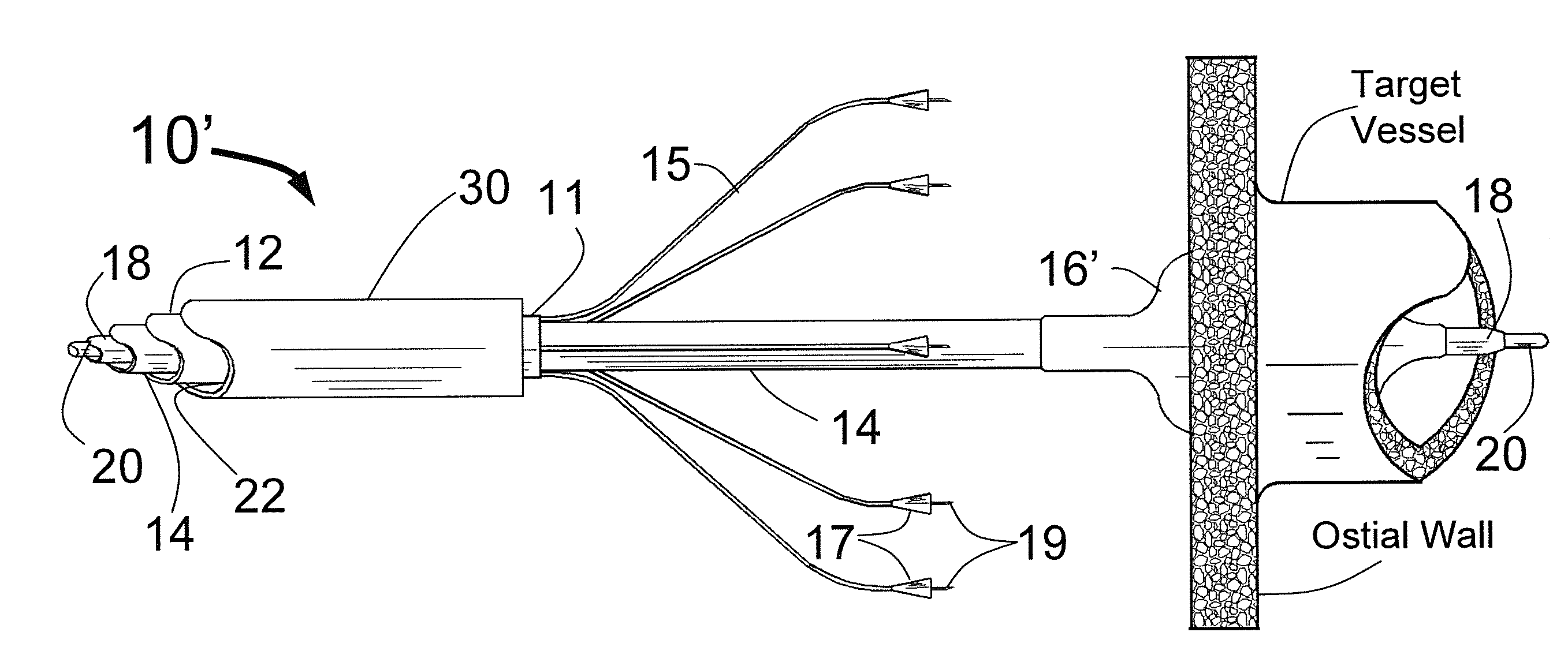
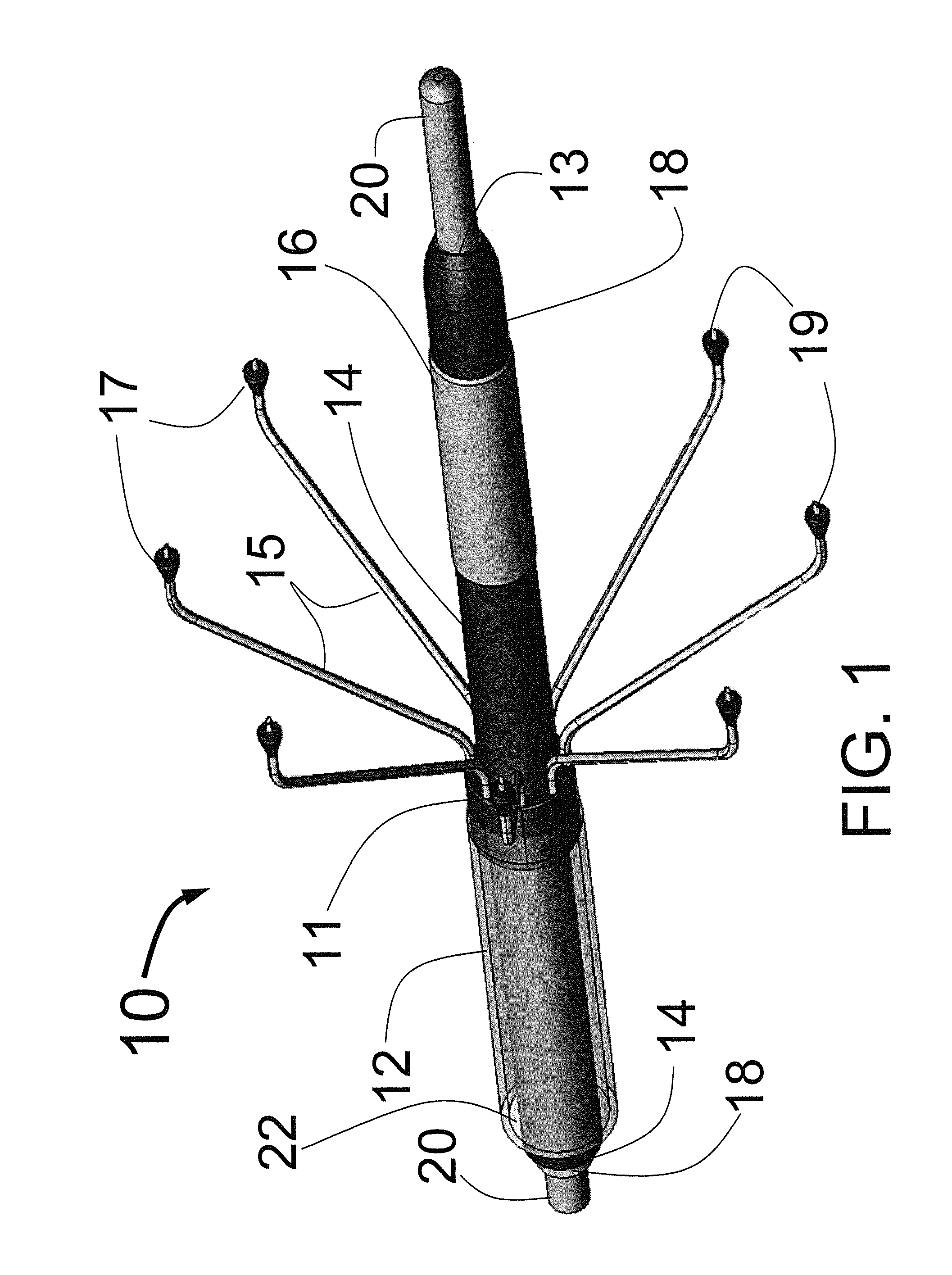
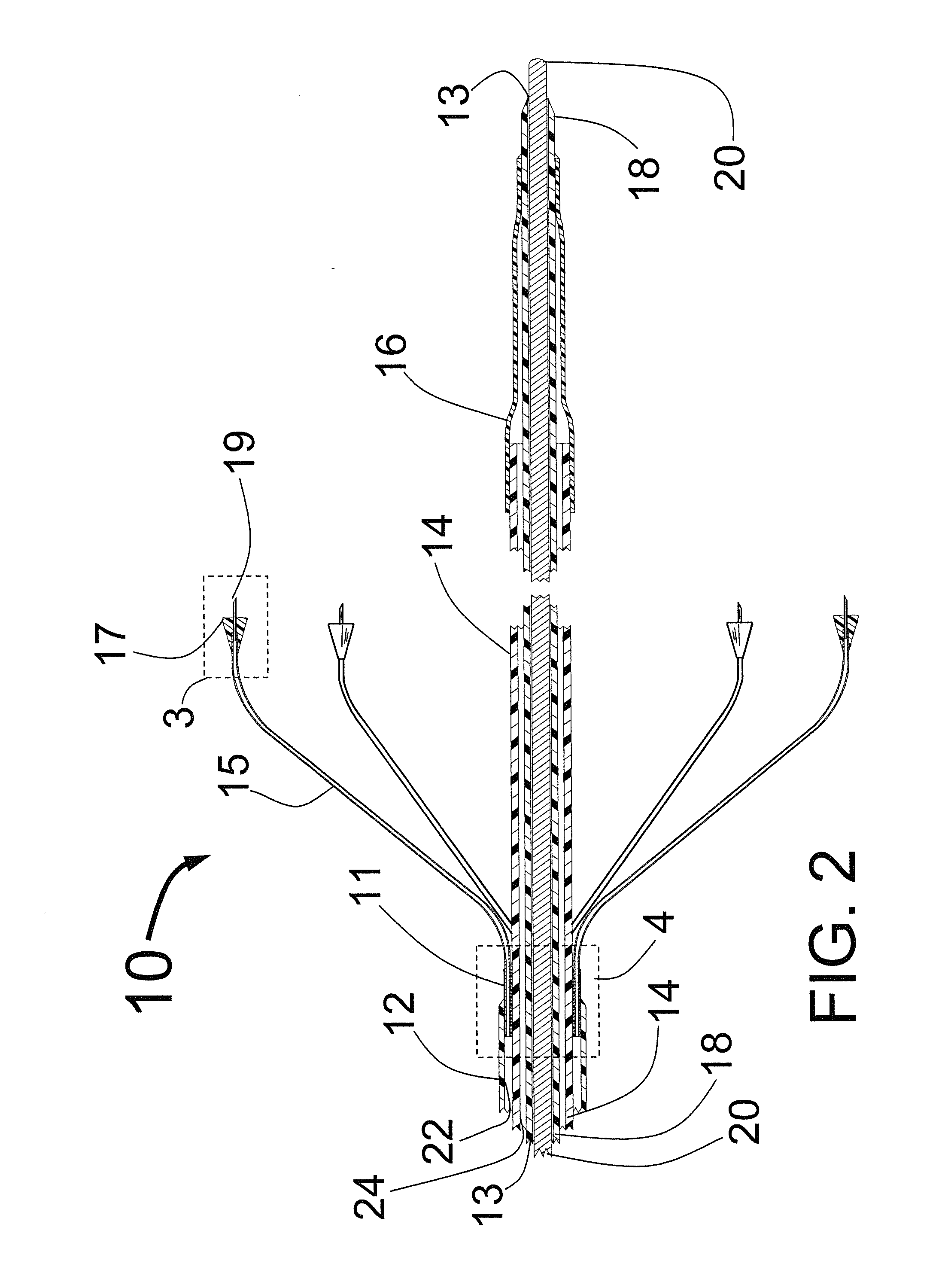
[0010]The present invention is a catheter which includes multiple expandable injector tubes arranged circumferentially around the body of the CAS near its distal end. Each tube includes an injector needle at its distal end. There is a penetration limiting member proximal to the distal end of each needle so that the needles will only penetrate into the tissue of the ostial wall to a preset distance. This will reduce the likelihood of perforation of the ostial wall and will optimize the depth of injection for each application. The injector needles are in fluid communication with an injection lumen in the catheter body which is in fluid communication with an injection port at the proximal end of the CAS. Such an injection port would typically include a standard connector such as a Luer connector used to connect to a source of ablative fluid.
[0013]The distal end of the CAS also includes a centering means at or near its distal end. The centering means could be a mechanical structure or an expandable balloon. The centering means will help to ensure that the injector tubes will be engaged circumferentially around and outside of the ostium of the target vessel. If the injector tubes are expanded by a balloon, then it is envisioned that the distal portion of the balloon would have conical or cylindrical distal portions that would facilitate centering the CAS in the target vessel.
[0015]The CAS might also be packaged to include an outer sheath that runs the entire length of the CAS so as to cover and protect the needles and also protect them from getting caught as the CAS is advanced distally to the desired location.
[0043]It is also envisioned that one could mount injector tubes with needles on the outer surface of an expandable balloon on the CAS in order to deliver 2 or more needles around the circumference of the ostium of a target vessel to inject ablative fluid to the ostial wall. In this case, the distal portion of the balloon could include the centering means of a cylindrical or conical shape. This embodiment could also include an elastic band covering the injector tubes where the elastic band could both help maintain a smooth outer surface of the CAS to facilitate delivery as well as act as the penetration limiting member to limit the penetration of the injection needles.

Problems solved by technology

In both cases these are elaborate and expensive catheter systems that can cause thermal, cryoablative, or other injury to surrounding tissue.
Many of these systems also require significant capital outlays for the reusable equipment that lies outside of the body, including RF generation systems and the fluid handling systems for cryoablative catheters.
In the case of atrial fibrillation ablation, the ablation of tissue surrounding multiple pulmonary veins can be technically challenging and very time consuming.
There is also a failure rate using these types of catheters for atrial fibrillation ablation.
The failures of the current approaches are related to the challenges in creating reproducible circumferential ablation of tissue around the ostium (peri-ostial) of a pulmonary vein.
There are also potential risks using the current technologies for RF ablation to create sympathetic nerve denervation inside the renal artery for the treatment of hypertension.
The long-term sequelae of applying RF energy inside the renal artery itself are unknown, but this could lead to late restenosis, embolization of debris into the renal parenchyma, or other problems inside the renal artery.
There may also be uneven or incomplete sympathetic nerve ablation, particularly if there are anatomic abnormalities, or atherosclerotic or fibrotic disease inside the renal artery, such that there is non-homogeneous delivery of RF energy.
This could lead to treatment failures, or the need for additional and dangerous levels of RF energy to ablate the nerves that run along the adventitial plane of the renal artery.
There are also significant safety issues with current technologies related to very long fluoroscopy and procedure times that lead to high levels of radiation exposure to both the patient and the operator, and may increase stroke risk in atrial fibrillation ablation.
Finally, while injection of ethanol as an ablative substance is used within the heart and other parts of the body, there has been no development of an ethanol injection system specifically designed for circular ablation of the ostial wall of a target vessel.

Method used


Image

  • Expandable catheter system for peri-ostial injection and muscle and nerve fiber ablation
  • Expandable catheter system for peri-ostial injection and muscle and nerve fiber ablation
  • Expandable catheter system for peri-ostial injection and muscle and nerve fiber ablation

Examples


Embodiment Construction

[0065]FIG. 1 is a three dimensional sketch of the distal end of the present invention Circular Ablation System (CAS) 10 in its state before it is loaded into a guiding catheter or sheath for delivery over the guide wire 20 into a human being. The proximal portion of the CAS 10 includes three tubes, an outer tube 12, a middle tube 14 and an inner tube 18. The guidewire 20 can be slidably advanced or removed through the guide wire lumen 13 inside of the inner tube 18. An expandable cylindrical balloon 16 is attached at its proximal end to the middle tube 14 and at its distal end to the inner tube 18. The balloon inflation lumen is located between the inner tube 18 and the middle tube 14. The balloon 16 can be inflated by injection of a fluid through the balloon inflation lumen and deflated by applying suction to the balloon inflation lumen.

[0066]A injector transition manifold 11 is sealed onto the outside of the middle tube 14. The outer tube 12 is sealed at its distal end onto the ou...


PUM


Abstract

At the present time, physicians often treat patients with atrial fibrillation (AF) using radiofrequency (RF) catheter systems to ablate conducting tissue in the wall of the Left Atrium of the heart around the ostium of the pulmonary veins. These systems are expensive and take time consuming to use. The present invention circular ablation system CAS includes a multiplicity of expandable needles that can be expanded around a central axis and positioned to inject a fluid like ethanol to ablate conductive tissue in a ring around the ostium of a pulmonary vein quickly and without the need for expensive capital equipment. The expansion of the needles is accomplished by self-expanding or balloon expandable structures. The invention includes centering means so that the needles will be situated in a pattern surrounding the outside of the ostium of a vein. Also included are members that limit the distance of penetration of the needles into the wall of the left atrium. The present invention also has application to ablating tissue around the ostium of a renal artery for the treatment of hypertension.

Description

FIELD OF USE[0001]This invention is in the field of devices to ablate muscle cells and nerve fibers for the treatment of cardiac arrhythmias and / or hypertension.BACKGROUND OF THE INVENTION[0002]At the present time, physicians often treat patients with atrial fibrillation (AF) using radiofrequency (RF) catheter systems to ablate conducting tissue in the wall of the Left Atrium of the heart around the ostium of the pulmonary veins. Similar technology, using radiofrequency energy, has been used inside the renal arteries to ablate sympathetic and other nerve fibers that run in the wall of the aorta on the outside of the renal arteries, in order to treat high blood pressure. In both cases these are elaborate and expensive catheter systems that can cause thermal, cryoablative, or other injury to surrounding tissue. Many of these systems also require significant capital outlays for the reusable equipment that lies outside of the body, including RF generation systems and the fluid handling ...

Claims


Application Information

Patent Timeline
Patent Type & Authority Applications(United States)
IPC IPC(8): A61B18/12
CPCA61B18/1492A61B2018/00214A61B2018/0022A61B2018/00375A61M5/00A61B2018/00434A61B2018/00511A61B2018/00577A61B2018/143A61B2018/00404
Inventor FISCHELL, DAVID R.FISCHELL, TIM A.
Owner ABLATIVE SOLUTIONS INC
Learn More