Optical touch module and method thereof

Inactive Publication Date: 2012-10-18
WISTRON CORP
View PDF10 Cites 1 Cited by
  • Summary
  • Abstract
  • Description
  • Claims
  • Application Information

AI Technical Summary

Benefits of technology

[0005]However, as mentioned above, since this design needs to additionally heighten the outer frame of the display panel for containing the optical sensing devices and the infrared light emitting units and the light reflection bars deform after being used over a period of time, this design can not only cause the problem that the appearance of the display panel is influenced and dust accumulate on the light reflection bars and the optical sensing devices easily, but also need to calibrate the position of the light reflection bar relative to the optical sensing device frequently. Furthermore, since the infrared light emitting unit (i.e. a spot light source) has different light intensity at different emitting angles and the probability that light is reflected back along its original incident path decreases greatly (only about 20%˜30%) when the light is incident into the light reflection bar at a large angle, the condition that signal attenuation of the light is too small when the touch object touches the touch surface at some specific position may occur in this design, so as to influence positioning accuracy of the optical sensing device.
[0007]The present invention further provides a method for positioning a touch object on a plane. The method includes disposing a transparent cover plate on the plane, disposing at least one light emitting unit along at least one side of the transparent cover plate and a light guide bar located at a light emitting side of the light emitting unit, disposing an optical sensing device on at least one corner side of the transparent cover plate, the light guide bar guiding light emitted by the light emitting unit into the transparent cover plate, the optical sensing device sensing a reduced optical signal caused by total internal reflection of the light in the transparent cover plate being frustrated at a position where a touch object touches the touch surface, and the optical sensing device positioning the touch object based on the reduced optical signal.

Problems solved by technology

However, as mentioned above, since this design needs to additionally heighten the outer frame of the display panel for containing the optical sensing devices and the infrared light emitting units and the light reflection bars deform after being used over a period of time, this design can not only cause the problem that the appearance of the display panel is influenced and dust accumulate on the light reflection bars and the optical sensing devices easily, but also need to calibrate the position of the light reflection bar relative to the optical sensing device frequently.

Method used


Image

  • Optical touch module and method thereof
  • Optical touch module and method thereof
  • Optical touch module and method thereof

Examples


Embodiment Construction

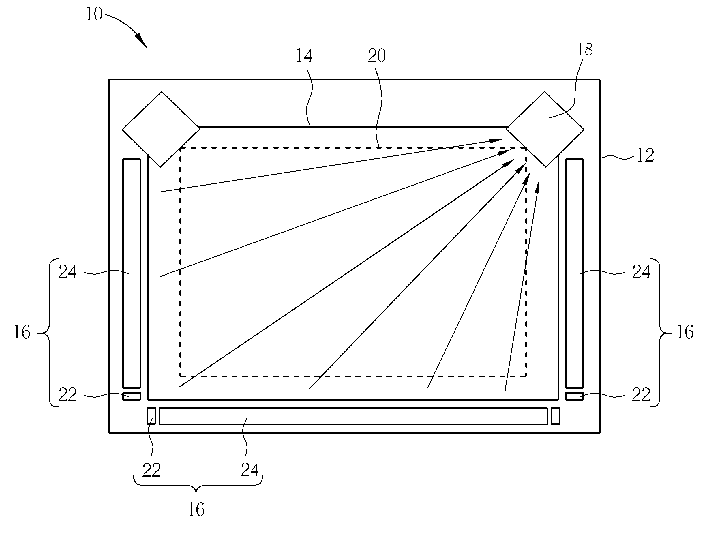
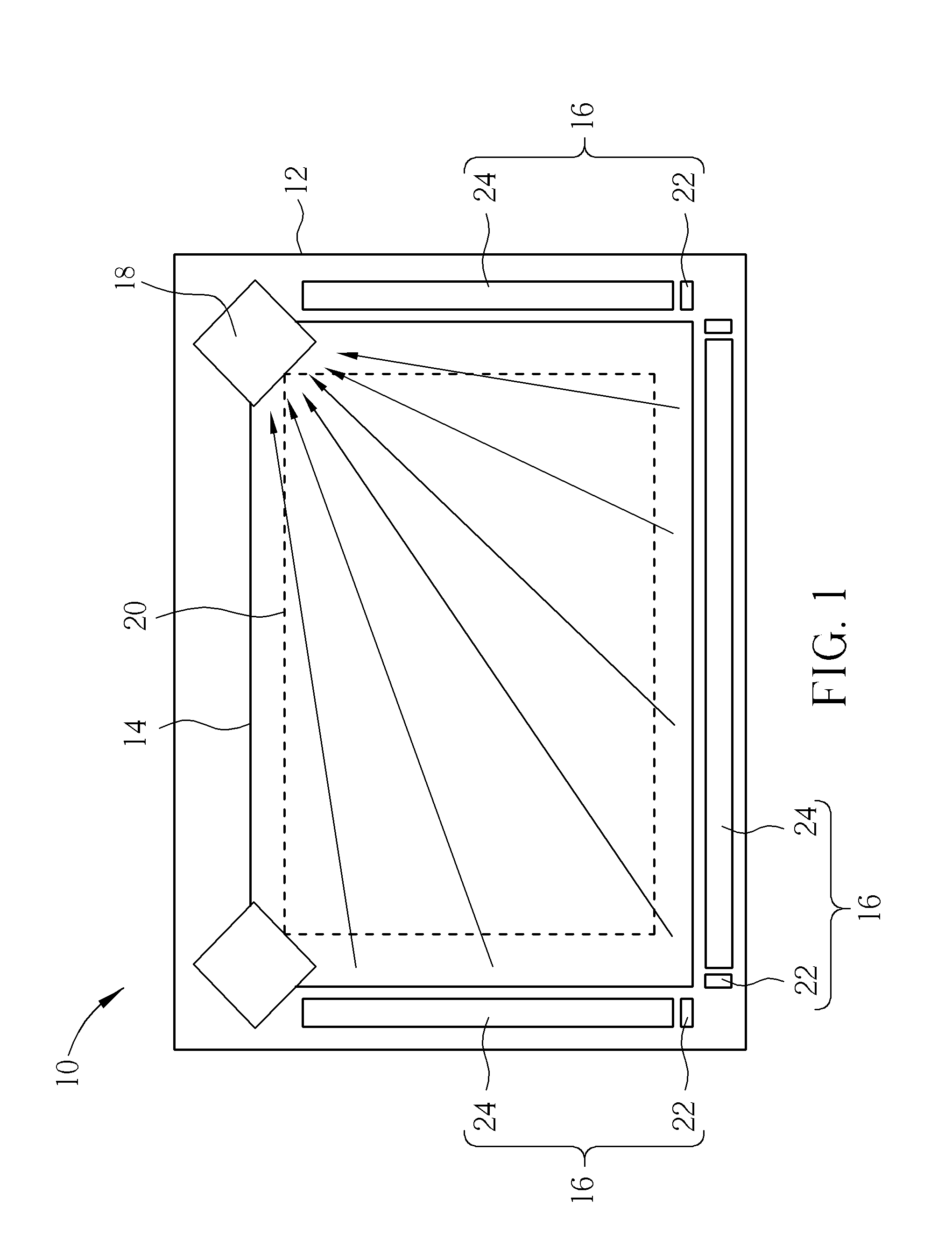
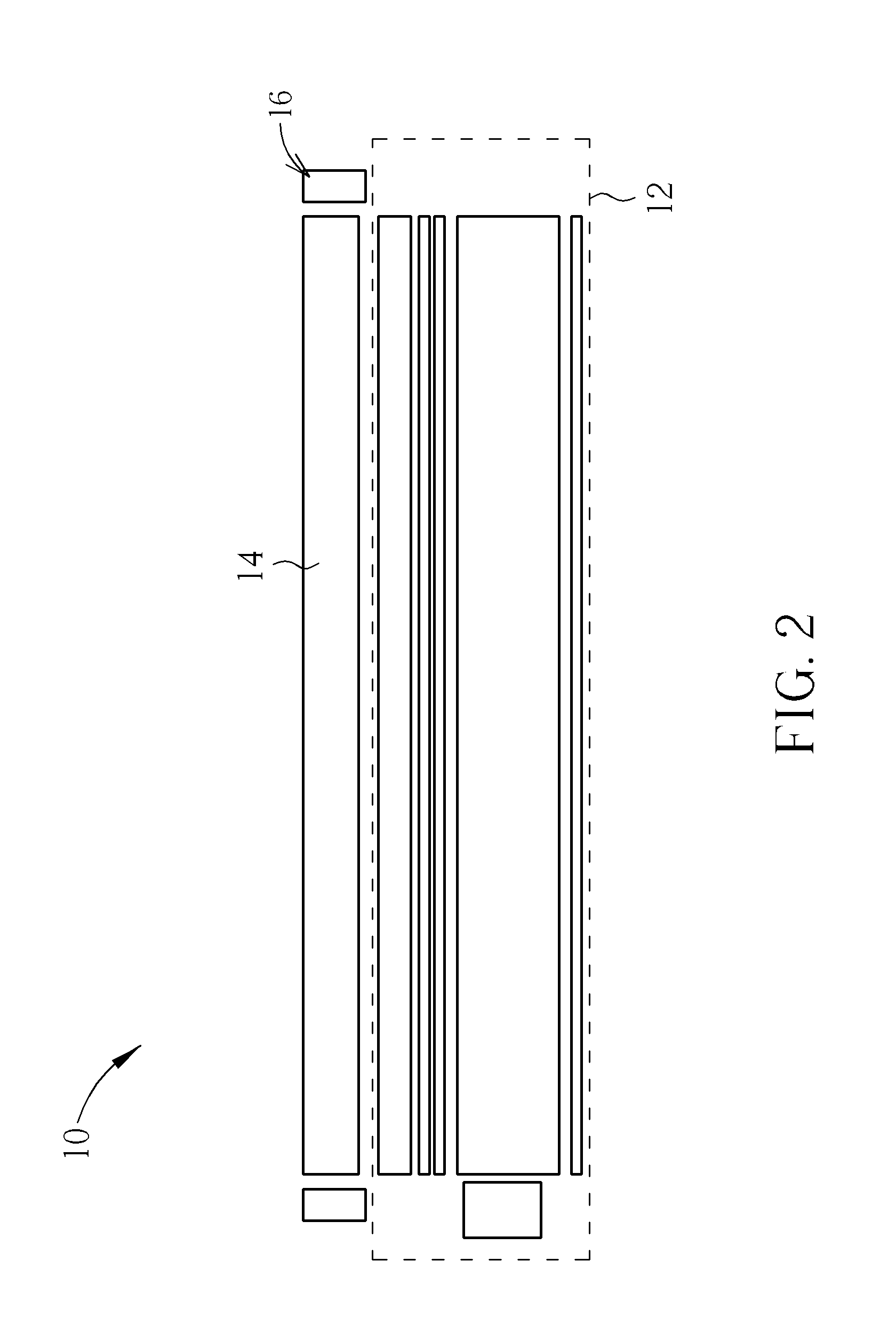
[0016]Please refer to FIG. 1 and FIG. 2. FIG. 1 is a front view of an optical touch module 10 according to an embodiment of the present invention. FIG. 2 is a side view of the configuration of the optical touch module 10 in FIG. 1. As shown in FIG. 1 and FIG. 2, the optical touch module 10 includes a transparent cover plate 14, at least one light bar device 16 (three shown in FIG. 1), and at least one optical sensing device 18 (two shown in FIG. 1). In the present invention, the optical touch module 10 is disposed on a plane, on which touch operations can be performed. In this embodiment, the plane is a display panel 12, but is not limited thereto. The display panel 12 includes components in a conventional display panel, such as a liquid crystal panel, a lens film, a diffusing film, a light guide plate, and a backlight source, and related description is omitted herein since it is commonly seen in the prior art. The transparent cover plate 14 is disposed on the display panel 12 and h...


PUM

PropertyMeasurementUnit
Angleaaaaaaaaaa
Angleaaaaaaaaaa
Angleaaaaaaaaaa

Abstract

An optical touch module includes a transparent cover plate, a light bar device, and an optical sensing device. The transparent cover plate has a touch surface. The light bar device is disposed along a side of the transparent cover plate, including a light emitting unit and a light guide bar. The light guide bar is disposed at a light emitting side of the light emitting unit for guiding light emitted by the light emitting unit into the transparent cover plate. The optical sensing device is disposed at a corner side of the transparent cover plate for sensing a reduced optical signal caused by total internal reflection of the light in the transparent cover plate being frustrated at a position where a touch object touches the touch surface. Accordingly, the optical sensing device can position the touch object based on the reduced optical signal.

Description

BACKGROUND OF THE INVENTION [0001]1. Field of the Invention[0002]The present invention relates to an optical touch module and a related method, and more specifically, to an optical touch module and a related method for positioning a touch object by frustrating total internal reflection of light in a transparent cover plate.[0003]2. Description of the Prior Art[0004]In general, a conventional design for optical touch positioning is to utilize a light interruption method to detect a position of a touch object on a touch surface. In this design, two optical sensing devices (e.g. a CMOS (Complementary Metal-Oxide Semiconductor) sensor) are respectively disposed at the left and right corners of a touch surface of a display panel, the overall height of which are higher than the touch surface of the display panel by about 3˜5 mm, infrared light emitting units are disposed near the optical sensing devices respectively, and a light reflection bar is disposed at the left, right, and bottom si...

Claims


Application Information

Patent Timeline
IPC IPC(8): G06F3/042H05K13/00
CPCG06F2203/04109Y10T29/49105G06F3/042
Inventor LIAO, CHING-HUAN
Owner WISTRON CORP
Why Eureka
Try Eureka