Vehicle door sash

a technology for doors and sashes, which is applied in the direction of doors, vehicle components, transportation and packaging, etc., can solve the problems of low degree of design flexibility of the joining portion, deterioration of the appearance of the door sash, and deterioration of the appearance, so as to achieve the effect of superior degree of design flexibility

Inactive Publication Date: 2017-05-25
SHIROKI KOGYO CO LTD
View PDF10 Cites 3 Cited by
  • Summary
  • Abstract
  • Description
  • Claims
  • Application Information

AI Technical Summary

Benefits of technology

[0021]According to the present invention, by forming the joining portion, which is positioned inside the inner frame portion with respect to the glass-run holding portion and the lip contacting portion, at the end of the glass run channel or the end portion of the inner frame portion, which is to be welded, a welding mark (e.g., weld bead) can be prevented from protruding inside the glass run channel, from protruding toward the sash inner peripheral side, or from being exposed to the sash inner peripheral side, thus making it possible to achieve a vehicle door sash in which a welding mark is less likely to interfere with a glass run and is less likely to adversely influence the appearance of the door. Additionally, since the vehicle door sash according to the present invention has a structure in which an end portion of the glass run channel and an end of the inner frame portion are welded, these ends do not have to be joined by hemming, and accordingly, the vehicle door sash according to the present invention is superior in degree of design flexibility compared with a hemming joint structure.

Problems solved by technology

In the structure, such as disclosed in the aforementioned publication, in which the outer end portion of the outer member and the inner end portion of the inner member are joined by hemming, there has been a problem with the joining portion having low in degree of design flexibility.
To increase the degree of design flexibility, it is possible to join the outer end portion and the inner end portion by welding instead of hemming; however, if the outer end portion and the inner end portion are joined by welding, there is a possibility of welding marks protruding inside the glass run channel to interfere with the glass run, thereby deteriorating the appearance of the door sash. FIGS. 11 and 12 each show a joining structure, of the related art, which easily causes such problems and in which the outer member and the inner member are joined to each other by welding.
In addition, there is a possibility of the weld bead W12 entering the visible range of the inner frame portion 56, thus deteriorating the appearance.
In the joining structures shown in FIGS. 11 and 12, to prevent the above described problems from occurring, it is required to perform a finishing operation in which the weld bead W11 and the weld bead W12 are substantially machined down, which makes the post-welding process troublesome.

Method used


Image

  • Vehicle door sash
  • Vehicle door sash
  • Vehicle door sash

Examples


first embodiment

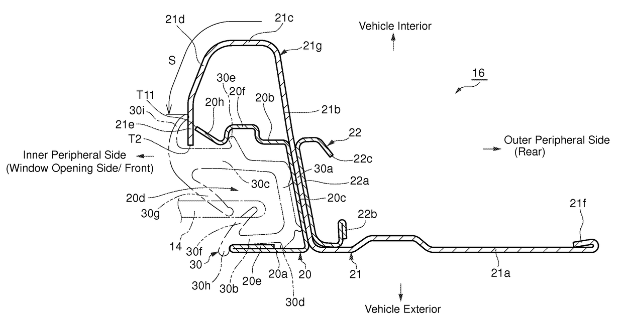
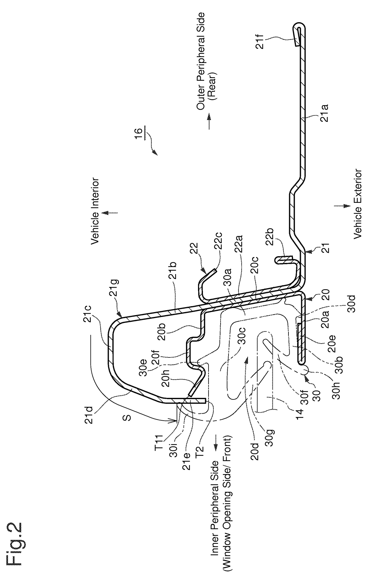
[0036]FIG. 2 shows the cross sectional structure of the side sash 16 according to the present invention. The side sash 16 is formed by combining an outer member 20, an inner member 21 and an auxiliary member 22. The outer member 20 is provided with a design portion (vehicle exterior side wall portion) 20a, a vehicle interior side wall portion 20b and a base wall 20c. The design portion 20a faces toward the vehicle exterior, the vehicle interior side wall portion 20b faces the design portion 20a and is positioned on the vehicle interior side, and the base wall 20c connects the outer peripheral side ends of the design portion 20a and the vehicle interior side wall portion 20b. The region of the side sash 16 which is surrounded by the design portion 20a, the vehicle interior side wall portion 20b and the base wall 20c is formed as a glass run channel 20d having a bottomed-groove sectional shape which is open to the inner peripheral side. The inner-peripheral-side end of the design port...

fourth embodiment

[0049]In the fourth embodiment shown in FIG. 7, bent end portions 21i which are shaped to increase the amount of projection thereof toward the inner peripheral side in a direction toward the vehicle exterior side are formed at the inner end portion of the vehicle exterior side flange 21e. Namely, the bent end portions 21i are shaped to bend in a direction away from the bent end portions 20h of the outer member 20. Each bent end portion 21i and the associated bent end portion 20h are joined by welding, thereby forming a weld bead (welding mark) W4 therebetween.

fifth embodiment

[0050]In the fifth embodiment shown in FIG. 8, a plurality of bent end portions 21j which are shaped to increase the amount of projection thereof toward the outer peripheral side in a direction toward the vehicle exterior side are formed at the inner end portion of the vehicle exterior side flange 21e. Namely, the bent end portions 21j are shaped to bend in a direction to approach the bent end portions 20h of the outer member 20. Each bent end portion 21j and the associated bent end portion 20h are joined by welding, thereby framing a weld bead (welding mark) W5 therebetween.

[0051]Thermal strain can be reduced by forming each welding part of the vehicle exterior side flange 21e which faces the associated bent end portion 20h into a bent end shape such as the bent end portion 21i or 21j. The bend angle of each bent end portion 21i, which is shaped to bend toward the inner peripheral side, is limited to a small degree of angle so that each bent end portion 21i does not interfere with ...


PUM


Abstract

A vehicle door sash includes an outer member having a glass run channel which is open to an inner peripheral side; an inner member positioned closer to a vehicle interior side than the glass run channel and includes an inner frame portion, end portions of the inner frame portion and the glass run channel are joined at the inner peripheral side; a glass-run holding portion provided on the end portion of the glass run channel to hold a side portion, of the glass run, which is positioned on the vehicle interior side; and a joining portion, provided on the end portion of the glass run channel, welded to the end portion of the inner frame portion, with an end of the joining portion positioned inside the inner frame portion relative to an end of the end portion of the inner frame portion and the glass-run holding portion.

Description

BACKGROUND OF THE INVENTION[0001]1. Field of the Invention[0002]The present invention relates to a vehicle door sash.[0003]2. Description of Related Art[0004]A structure for door sashes constituting components of a vehicle door (for example, side sashes (upright pillar sashes) that extend along a center pillar) in which an outer member that is a molded article and is provided with a glass run channel for holding a glass run, and an inner member that is a molded article and includes an inner frame portion that projects toward the vehicle interior with respect to the glass run channel are joined together to form a sash, is known in the art. The glass run channel of the outer member has the shape of a channel section which is open toward the sash inner periphery, on which a window opening is formed, and the inner frame portion of the inner member has a sack-like sectional shape which is open to the vehicle exterior. After the inner member and the outer member are combined so that the o...

Claims


Application Information

Patent Timeline
Patent Type & Authority Applications(United States)
IPC IPC(8): B60J5/04
CPCB60J5/0463B60J5/0402
Inventor MAKITA, JUN
Owner SHIROKI KOGYO CO LTD
Why Eureka
Try Eureka