Diaphragm

a technology of diaphragm and lung, which is applied in the field of diaphragm for lung demand valve, can solve the problems of increased complexity and therefore cost of lung demand valve when compared with a conventional lung demand valv

Active Publication Date: 2012-10-18
DRAEGER SAFETY UK
View PDF5 Cites 2 Cited by
  • Summary
  • Abstract
  • Description
  • Claims
  • Application Information

AI Technical Summary

Problems solved by technology

Whilst the above described arrangements may be appropriate in some circumstances, the complexity and therefore cost of the lung demand valve is increased when compared with a conventional lung demand valve.

Method used


Image

  • Diaphragm
  • Diaphragm
  • Diaphragm

Examples


Embodiment Construction

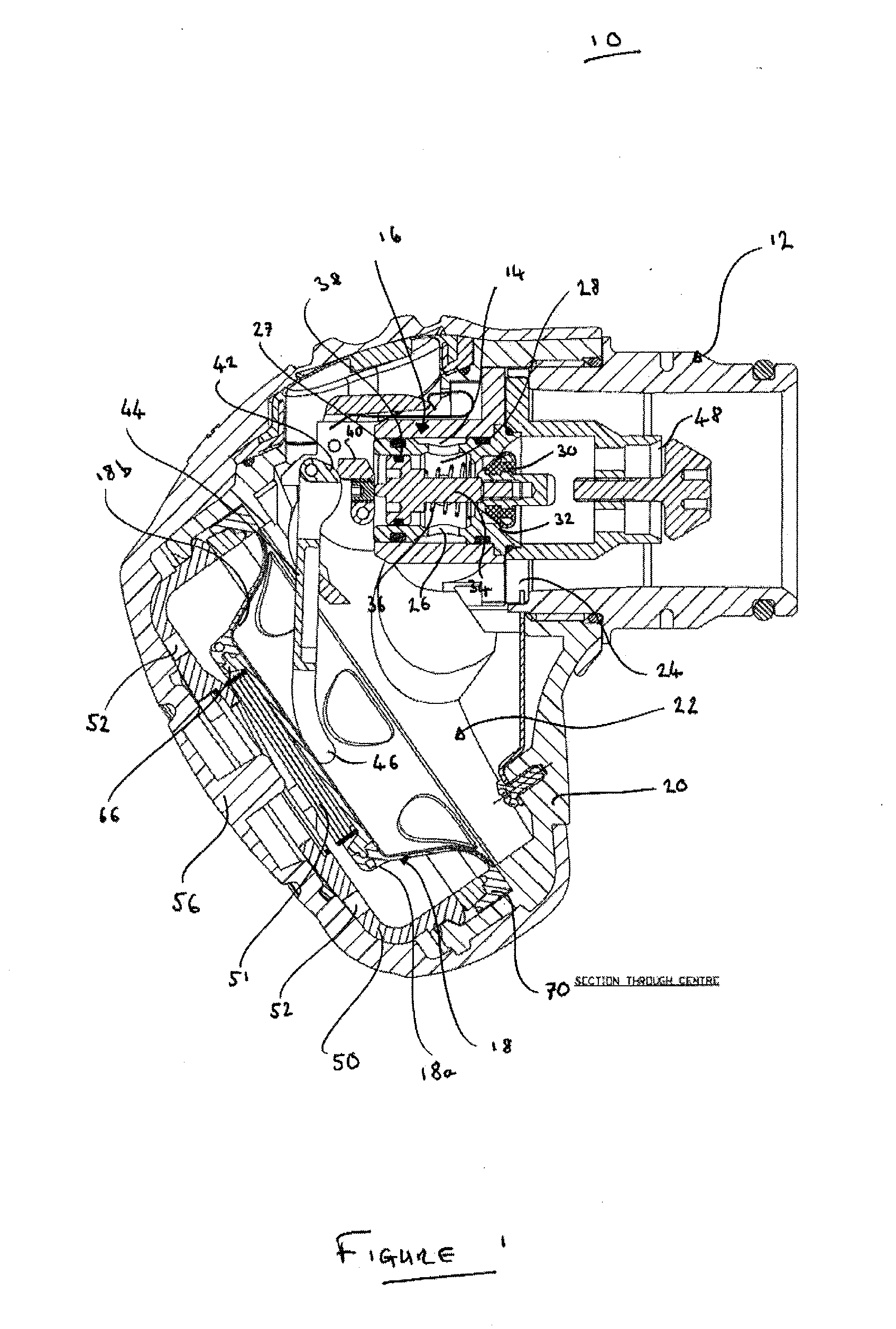
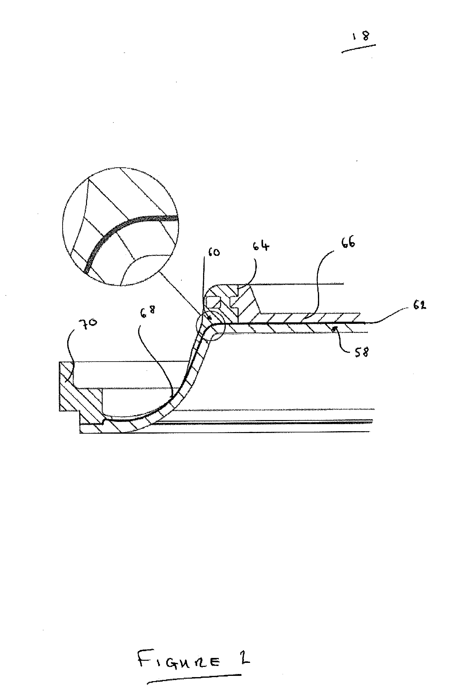
[0016]In a broad aspect the invention concerns a CBRN or barrier layer of a diaphragm for a lung demand valve that is arranged to restrict the permeation of at least some CBRN agents through the diaphragm.

[0017]The term “CBRN” will be used throughout the description and claims and is an acronym for “chemical, biological, radiological and / or nuclear.”

[0018]According to an aspect of the invention there is provided a diaphragm for a lung demand valve, comprising: a CBRN (or barrier) layer which is sufficiently resistant to the permeation of at least some CBRN (or hazardous) agents; and a resilient layer which is resiliently deformable; wherein the CRBN (or barrier) layer is arranged to restrict the permeation of at least some CBRN (or hazardous) agents through the diaphragm, and wherein the resilient layer is arranged to allow the diaphragm to be resiliently deformed. The diaphragm may be suitable for use in at least some CBRN or hazardous environments. The CBRN layer may be referred t...


PUM

PropertyMeasurementUnit
thicknessaaaaaaaaaa
thicknessaaaaaaaaaa
thicknessaaaaaaaaaa

Abstract

A diaphragm for a lung demand valve, including a chemical, biological, radiological and / or nuclear (CBRN) layer which is sufficiently resistant to the permeation of at least some CBRN agents and a resilient layer which is resiliently deformable. The CRBN layer is arranged to restrict the permeation of at least some CBRN agents through the diaphragm, and the resilient layer is arranged to allow the diaphragm to be resiliently deformed.

Description

CROSS REFERENCE TO RELATED APPLICATIONS[0001]This application claims the priority of UK Patent Application No. 1106479.7 filed on Apr. 18, 2011 and UK Patent Application No. 1204044.0 filed on Mar. 7, 2012, the entire contents of which are incorporated herein by reference.BACKGROUND OF THE INVENTION[0002]The invention relates to a diaphragm for a lung demand valve, in particular, although not exclusively, to a lung demand valve suitable for use in CBRN environments.[0003]A lung demand valve (LDV) is typically used with breathing apparatus in order to control the supply of breathable gas to the user. An LDV usually comprises a flexible diaphragm that responds to pressure changes so as to control the flow of the breathable gas. A first side of the diaphragm is exposed to ambient pressure and the second side of the diaphragm is exposed to the pressure within the face-mask. The diaphragm is typically manufactured from an elastomer such as silicone.[0004]If the LDV is to be used in chemi...

Claims


Application Information

Patent Timeline
Patent Type & Authority Applications(United States)
IPC IPC(8): A61M16/20
CPCA62B9/027A62B18/10A62B7/04F16K7/12B01D2257/2064B01D2257/2066B01D2258/06B01D2259/4533B01D2259/4583Y10T29/4973B01D53/22A62B9/02A62B9/022A62B7/10F16K7/17F16K31/1262
Inventor TOWNSEND, PAUL
Owner DRAEGER SAFETY UK
Why Eureka
Try Eureka