
Lacrosse stick pocket and related method of manufacture

a technology of lacrosse stick and manufacturing method, which is applied in the field of lacrosse equipment, can solve the problems of difficult to accommodate these players, difficult to replace, and difficult to adapt to the needs of players, and achieves the effect of convenient replacemen

Inactive Publication Date: 2012-10-11
WARRIOR SPORTS INC
View PDF0 Cites 27 Cited by
  • Summary
  • Abstract
  • Description
  • Claims
  • Application Information

AI Technical Summary

Benefits of technology

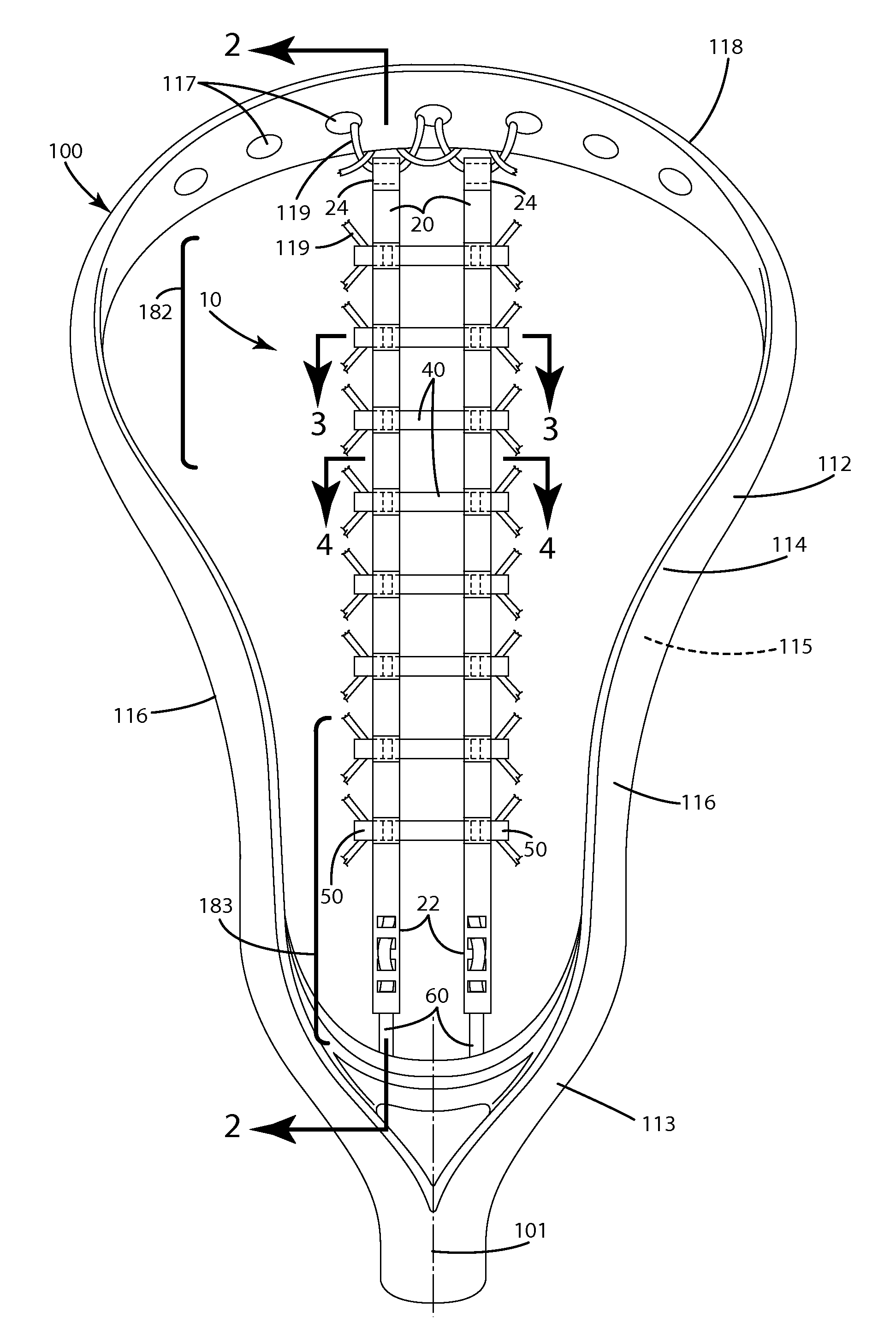
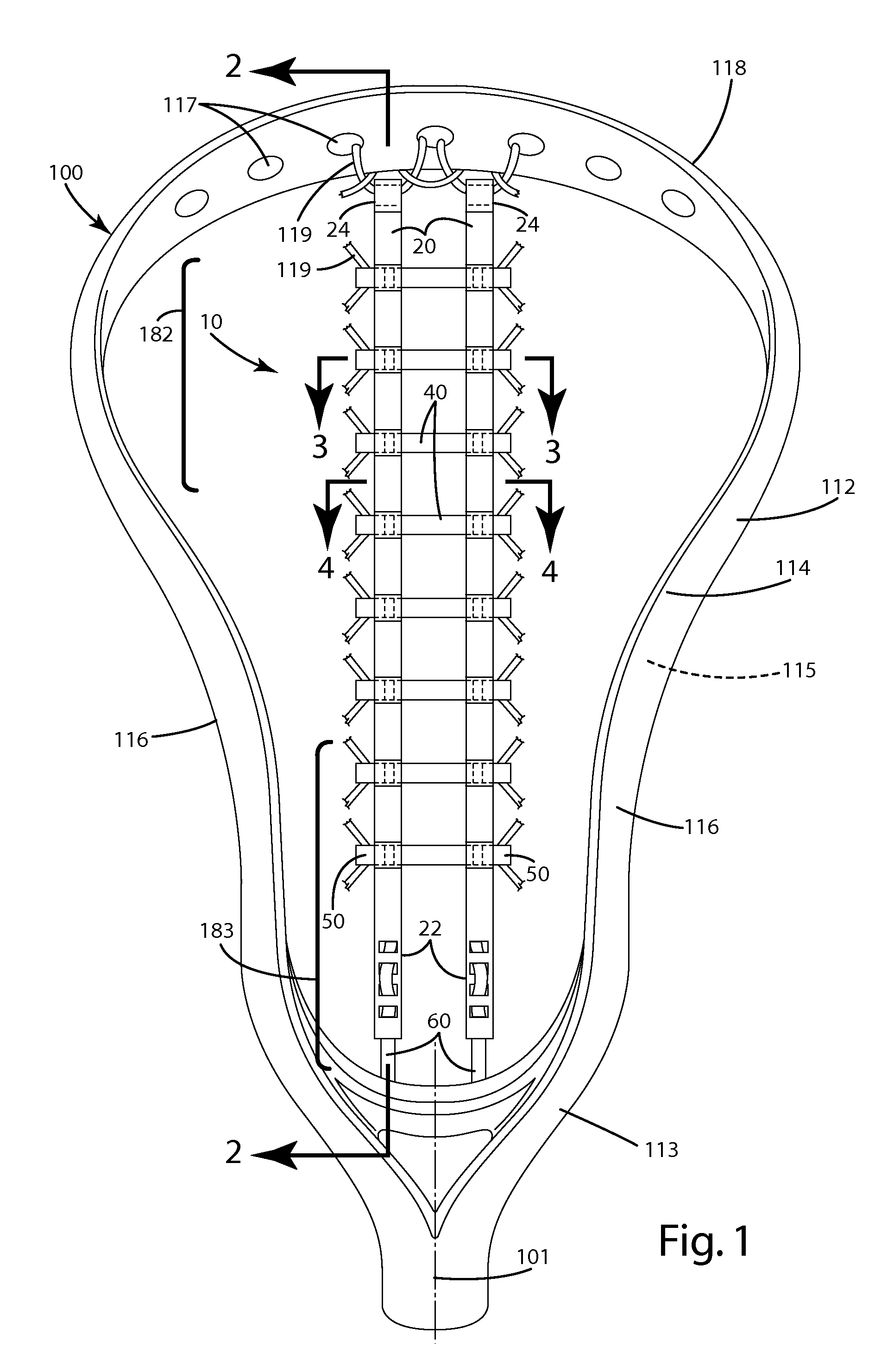
[0008]A lacrosse head is provided that includes a pocket that is durable and easy to replace relative to the lacrosse head. A method for making the pocket is also provided.
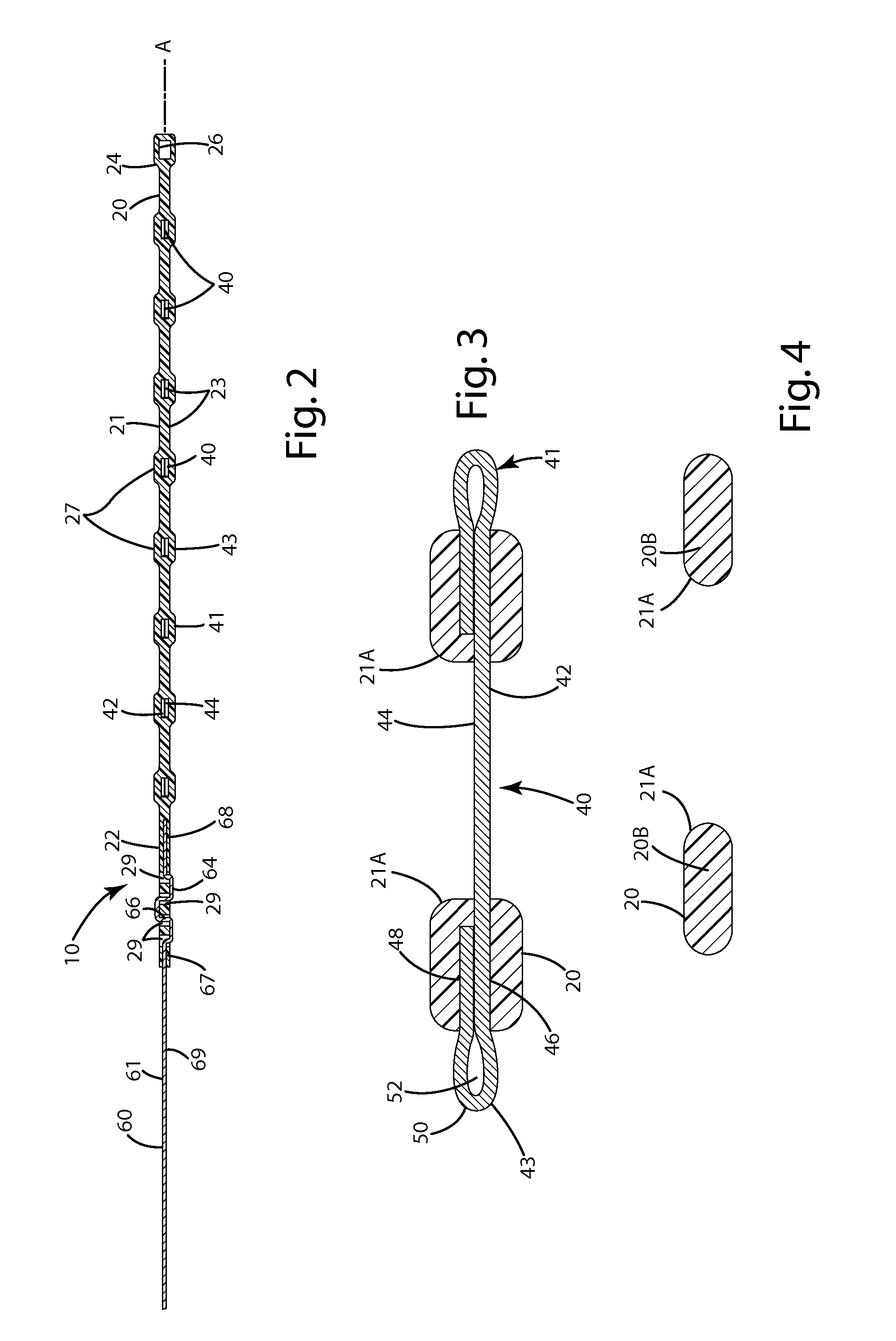
[0012]In still another alternative embodiment, a method for manufacturing a lacrosse pocket is provided. The method includes forming portions of a single layer runner with a chamfered and / or rounded contact surface on a side opposite to the side having a speed loop. The chamfered and / or rounded contact surface reduces surface variations along portions of the single layer runner that contact a lacrosse ball during use, and also increases the area of contact between the single layer runner and the lacrosse ball during use. The chamfered and / or rounded contact surface can also help channel the ball specifically and consistently along a desired shooting channel defined by the opposing single layer runners. In turn, this can provide improved directional control on the ball, and thereby improve the accuracy of shooting from the pocket.
[0024]The lacrosse pocket and method herein provide a lacrosse net structure that is easily replaceable relative to a lacrosse head, even by youth and newcomers to the sport. Multiple different, custom pocket profiles can be formed with the present method, thereby offering a high degree of pocket customization to lacrosse players, without those players having to have significant knowledge and experience in shaping and fitting a pocket, and without having to pay someone else to install the netting structure.
[0025]Further, where the material is constructed from hydrophobic or waterproof materials, the netting is virtually unaffected by weather changes, temperature changes and moisture, which enables it to have a substantially consistent profile and configuration throughout such conditions. In turn, this enables the player to play with confidence, even under adverse environmental conditions.

Problems solved by technology

With many conventional pockets, however, it is frequently difficult to accommodate these player preferences without significant knowledge and experience about how to modify the netting so that the pocket has a specific profile and performs as desired.
Further, when conventional pockets wear out after extensive play, the mere thought of replacing it can be daunting to many, particularly younger or less experienced lacrosse players.
In addition to conventional lacrosse pockets being difficult to customize and replace, they usually are affected by climate.
For example, even where netting is woven or otherwise constructed from filaments of nylon or polypropylene, when wetted by a rain, the netting of the pocket can shrink or become slippery, which can significantly alter how a lacrosse ball is shot from the pocket.
This can lead to inconsistent shooting, which can be detrimental to the player's performance.
Some manufacturers have attempted to resolve the above issues, but few have succeeded.
While this construction provides an easy-to-install runner system, it requires a skill to precisely position and connect the cross pieces to the multilayered runners, which skill may not be possessed by younger or inexperienced players.
Moreover, although the polyurethane and braided nylon layers work well, the layering of different materials requires additional assembly time.
The extra machine stitching and sewing to join the various layers also requires additional assembly time and resources.

Method used


Image

  • Lacrosse stick pocket and related method of manufacture
  • Lacrosse stick pocket and related method of manufacture
  • Lacrosse stick pocket and related method of manufacture

Examples


second alternative embodiment

IV. Second Alternative Embodiment

[0102]A second alternative embodiment of the lacrosse pocket 210 is illustrated in FIGS. 11-15. This pocket 210 is generally identical to the pocket of the current embodiment described above, with several exceptions. For example, the runners 220 include a core 264 that is overmolded. The core 264 is joined with the throat tie 260. The core 264 can be constructed from the same material as the throat tie, and can extend from the ball stop end 222 to the scoop end 224 of the runners 220, as shown in FIG. 12. The core 264 can terminate short of the opening 226 defined by the scoop end 224, or it can form an end loop (not shown).

[0103]With reference to FIGS. 13 and 14, core 264 can be embedded in and generally encapsulated by the surrounding overmolded material 223. In the region of the cross pieces 240, the core 264 can be secured between different portions of the lacrosse piece. For example, where the end of the cross piece 240 is doubled back over on i...

third alternative embodiment

V. Third Alternative Embodiment

[0105]The third alternative embodiment of the lacrosse pocket 310 is illustrated in FIGS. 16 and 17. This pocket 310 includes single layer runners 320 that are similar to the single layer runners of the current embodiment with several exceptions. For example, the runners 320 are overmolded over the respective cross pieces 340 in a slightly different manner. As shown in FIG. 16, the single layer runner 320 is molded over the cross pieces 340, it contacts and engages primarily the upper surface 342 and the sides 343 of the cross piece. The rear surface 344 of the cross piece remains generally uncovered by the overmolded polymeric material. In turn, the rear surface 344 of the cross pieces remain exposed and viewable in the finished lacrosse pocket 310. As with the current embodiment, the finished single layer runner is the only structure that spans between and joins the cross pieces 340. If desired, an optional fastening structure, such as a stitch 382, ...

fourth alternative embodiment

VI. Fourth Alternative Embodiment

[0106]A fourth alternative embodiment of the lacrosse pocket is illustrated in FIGS. 18-19. The lacrosse pocket of this embodiment is generally the same as the above embodiments with several exceptions. For example, the runner 420 includes a layer 464 of a second material that is different from the overmolded material 445. This second material can be a nylon web, braided material or any of the other materials described above. The second layer 464 can include an upper surface 466 that generally faces the front side of the head 114, and a rear surface 467 which generally faces the rear side of the lacrosse head 115. Cross pieces 440 are joined with the second layer 464 of the runners 420. In general, the cross pieces 440 are laid across the front surfaces 466 of the second layer 464. The rear surface 444 of the cross pieces can generally engage the front surface 466.

[0107]The cross pieces 440 can be joined with fastening structures to the second layer ...


PUM

PropertyMeasurementUnit
thicknessaaaaaaaaaa
total thicknessaaaaaaaaaa
widthaaaaaaaaaa

Abstract

A lacrosse head pocket includes an elongated single layer runner with multiple cross pieces. The single layer runner can be constructed from a material, such as a polymeric material, molded over the cross pieces. The cross pieces and / or runner can include speed lace loops with which a net lace can be joined. A related method includes providing cross pieces, overmolding a polymeric material over the cross pieces to form a single layer runner, where the overmolded material is the only structure extending between and connecting the cross pieces, and where the cross pieces are transverse to the runners. Another method includes providing a pocket base overmolding the base with a polymeric material to cover portions of it, and forming connection elements between different portions independently of any other components of the pocket base.

Description

BACKGROUND OF THE INVENTION[0001]The present invention relates generally to lacrosse equipment, and more particularly, to a lacrosse stick pocket and a related method of manufacture.[0002]Conventional lacrosse sticks include a head joined with a handle. The head includes a frame that forms a region within which a lacrosse ball can be caught, held or shot. A netting structure is joined with the back side of the frame, typically laced through multiple small holes defined by the frame. The netting structure typically forms a pocket within which the ball is held while a player is in possession of the ball, and can be a determinant factor as to the player's ability to catch, retain and shoot the ball.[0003]Typically, different players at different positions prefer pockets having certain properties and certain configurations. For example, while a player at an attack position generally prefers a relatively shallow pocket for the quick release and accurate shooting of a lacrosse ball, a mid...

Claims


Application Information

Patent Timeline
Patent Type & Authority Applications(United States)
IPC IPC(8): B32B37/14B32B37/12
CPCY10T156/1002A63B59/02A63B2243/005A63B2209/00A63B2102/14A63B59/20
Inventor WINNINGHAM, MATTHEW M.PAQUETTE, ADAM D.HANSON, JESSICA L.JANISSE, RICHARD J.
Owner WARRIOR SPORTS INC
Learn More