
Grid tied inverter, system and method

a technology of inverters and grids, applied in the direction of electric variable regulation, process and machine control, instruments, etc., can solve the problems of high cost and large size of inverters

Inactive Publication Date: 2012-10-04
SONY CORP
View PDF4 Cites 16 Cited by
  • Summary
  • Abstract
  • Description
  • Claims
  • Application Information

AI Technical Summary

Benefits of technology

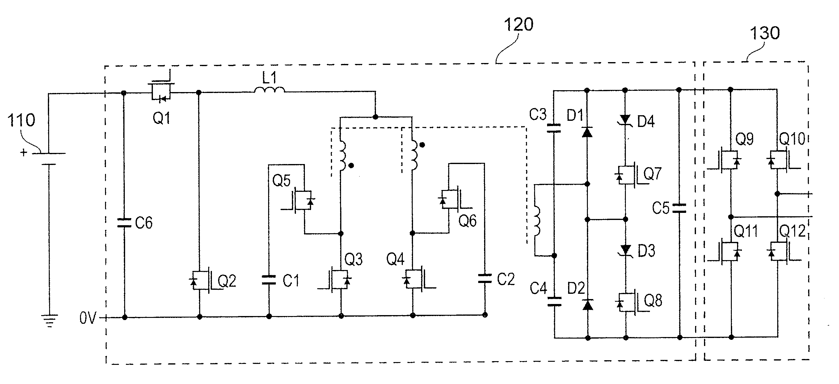
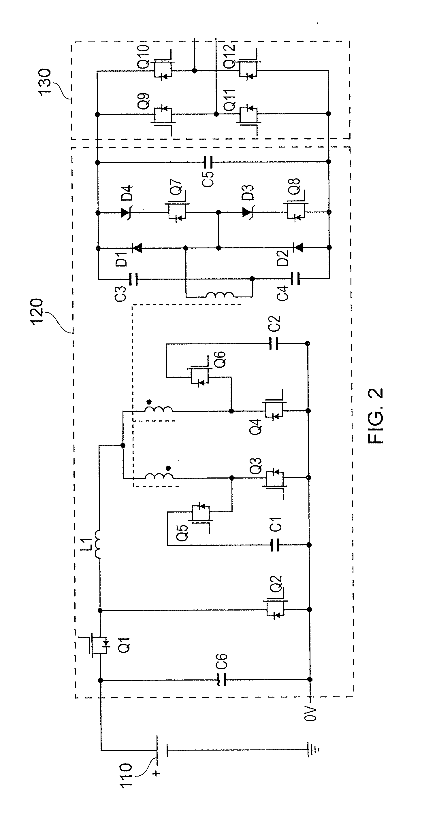
[0013]The first side of the transformer may have a first winding which is connected to a first transistor switch and a second transistor switch, the second transistor switch is a field effect transistor having the anode of the body diode connected to the first winding, whereby the first switch is connected to ground and the second switch is connected to a first capac

Problems solved by technology

These inverters tend to be very large and expensive.

Method used


Image

  • Grid tied inverter, system and method
  • Grid tied inverter, system and method
  • Grid tied inverter, system and method

Examples


Embodiment Construction

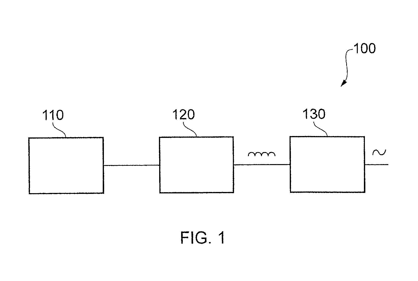
[0025]With reference to FIG. 1, a system 100 is shown. The system 100 comprises a battery 110, a DC to DC converter 120 and an unfolding circuit 130. The DC to DC converter 120 and the unfolding circuit 130 form the grid tied inverter according to embodiments of the invention. The unfolding circuit 130 is connected to a mains electricity supply provided by the mains electricity grid (not shown) and the DC to DC converter 120 is connected to the battery 110.

[0026]The battery 110 is, in embodiments, a 2 kWh battery which is typically made up of a number of battery cells. Each battery cell may be rated at 30 Ah. The battery 110 is a DC voltage source capable of delivering around 1 kW of power at any one time. The invention is not however, limited to this and any size and type of battery may be also used in embodiments.

[0027]The grid tied inverter is connected to the battery 110. The DC to DC converter 120 is connected to the battery 110 using, in embodiments, standard IEC form power in...


PUM


Abstract

A grid tied inverter connectable to an electricity grid, the grid tied inverter comprising a DC to DC current fed push-pull converter operable to generate a current waveform from a DC voltage source, the current waveform being substantially synchronised to the electricity grid, the push-pull converter comprising a transformer having a first side connectable to a battery and a second side connectable to the grid, wherein each of the two primary sides is connected to ground via a switching transistor; andrespective voltage clamps are connected between the respective primary side of the transformer and the respective switching transistor, the voltage clamp commutating the current from the respective primary side of the transformer when the switching transistor is turned off.

Description

BACKGROUND OF THE INVENTION[0001]1. Field of the Invention[0002]The present invention relates to a grid tied inverter, method and system.[0003]2. Description of the Prior Art[0004]It is becoming increasingly attractive for domestic consumers of electricity to provide electricity for the grid. This is particularly important given the rapid increase in electricity usage, especially during peak demand.[0005]It is possible to provide this electricity using so-called “Grid-Tied Inverters”. These are DC-DC converters which connect banks of batteries to the grid. These inverters tend to be very large and expensive.[0006]It is an aim of the present invention to address these issues.SUMMARY OF THE INVENTION[0007]According to a first aspect, there is provided a grid tied inverter connectable to an electricity grid, the grid tied inverter comprising a DC to DC current fed push-pull converter operable to generate a current waveform from a DC voltage source, the current waveform being substantia...

Claims


Application Information

Patent Timeline
IPC IPC(8): H02M7/5387H02M3/335
CPCH02J3/32H02J3/381H01F2027/2819H02M7/48H02M2001/007H02M3/33569H02M1/007H02J3/40H02M3/3376
Inventor KNILL, ALEXANDER CHARLES
Owner SONY CORP
Learn More