
Inkjet printer

a technology of inkjet printers and inkjet printers, applied in printing and other directions, can solve the problems of backflow leakage of moisture from the moisture discharge head or leakage of moisture in the moisture supply path, and easy clogging of the ink nozzle,

Active Publication Date: 2012-10-04
SEIKO EPSON CORP
View PDF13 Cites 13 Cited by
  • Summary
  • Abstract
  • Description
  • Claims
  • Application Information

AI Technical Summary

Benefits of technology

[0022]A valve located in a moisture supply path is opened only when the fluid nozzle face of a moisture discharge head is sealed with a cap by the valve operating mechanism, and is closed when the fluid nozzle face is not covered by the cap. Leakage of moisture from the moisture discharge head, and backflow of moisture from the moisture discharge head to the moisture tank side can therefore be prevented or reduced.

Problems solved by technology

As a result, the ink nozzles become easily clogged.
However, leakage of moisture from the moisture discharge head or backflow of the moisture in the moisture supply path could occur depending on the location of the moisture tank.
If the moisture leaks, the inside of the printer could become wet.
If moisture backflow occurs, the amount of moisture discharged into the cap by the suction operation of the suction pump will be unstable, and the moisture level inside the cap cannot be kept at the desired level.
However, if the diameter of the fluid nozzle is on the order of several ten microns, a hydraulic head of several hundred millimeters cannot be withstood, manufacturing the moisture discharge head is therefore more difficult, and the product manufacturing cost increases.

Method used


Image

  • Inkjet printer
  • Inkjet printer
  • Inkjet printer

Examples


Embodiment Construction

[0031]An inkjet printer according to a preferred embodiment of the invention is described below with reference to the accompanying figures.

General Configuration

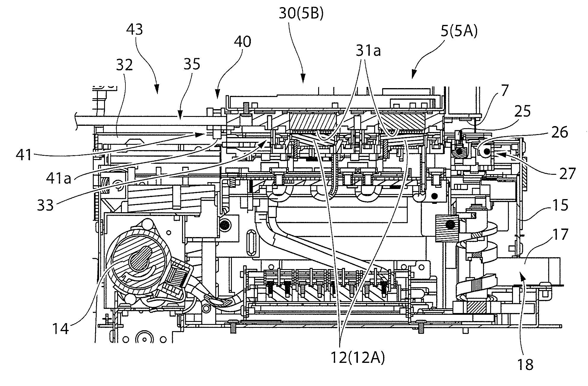
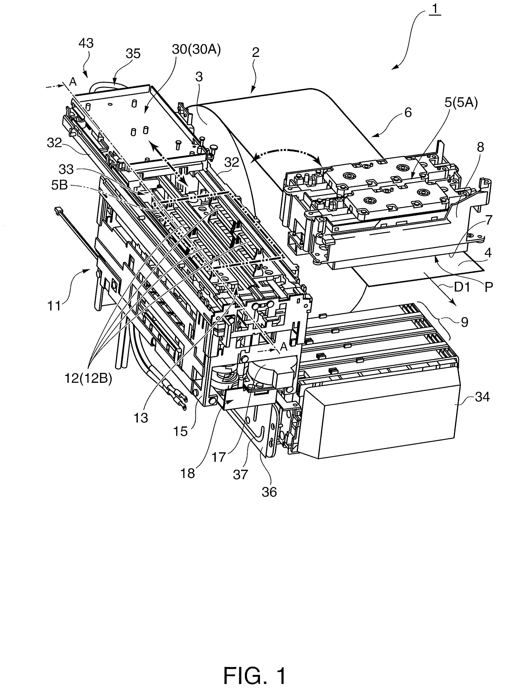
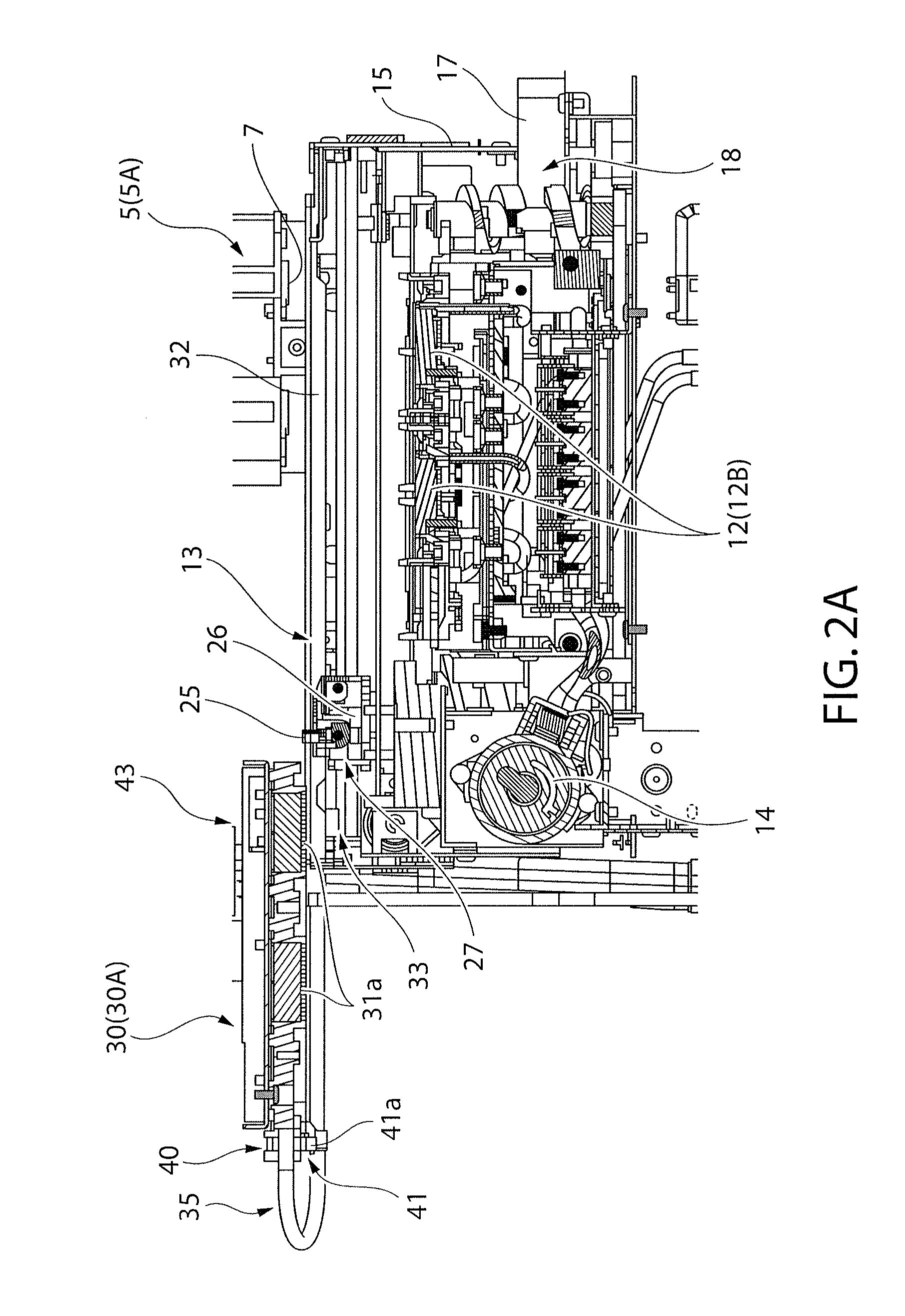
[0032]FIG. 1 is an oblique view showing main parts of an inkjet printer according to this embodiment of the invention with the printer case removed. FIG. 2 is a section view through line A-A in FIG. 1, FIG. 2A showing the moisture discharge head at the maintenance standby position, and FIG. 2B showing the moisture discharge head at the maintenance position. FIG. 3 is an oblique view of the moisture discharge head, moisture supply path, and guide rail from below the back of the printer.

[0033]As shown in FIG. 1, the inkjet printer 1 conveys recording paper 4 pulled from a paper roll 3 stored in a roll paper compartment 2 at the back of the printer in a conveyance direction D1 toward the front of the printer along a roll paper conveyance path 6 past the printing position P of the inkjet head 5, and prints. The inkjet head 5 is m...


PUM


Abstract

An inkjet printer has a valve unit in a moisture supply path that connects a moisture tank and the fluid nozzles of a moisture discharge head. The moisture discharge head has an operating lever for opening and closing the valve unit, and when the cap approaches the moisture discharge head to seal the fluid nozzle faces of the moisture discharge head, a wiper unit that moves with the cap depresses the operating lever and opens the valve unit. Because the valve unit is open while the fluid nozzle faces are sealed by the cap, moisture leakage and backflow are suppressed.

Description

BACKGROUND[0001]1. Technical Field[0002]The present invention relates to an inkjet printer that has a cap to cover the ink nozzle face of the inkjet head, and a moisture supply mechanism that supplies a moisturizing fluid into the cap.[0003]2. Related Art[0004]In order to prevent an increase in the viscosity of ink in the ink nozzles from clogging the ink nozzles, inkjet printers cover the ink nozzle face in which the ink nozzles are formed with a cap while the inkjet head is at the maintenance position to suppress evaporation of moisture from the ink nozzles. A flushing operation that ejects ink from the ink nozzles into the cap while the cap is opposite the ink nozzle face is also regularly performed to suppress nozzle clogging. When ink nozzle clogging occurs, an ink suction operation that covers the ink nozzle face with a cap, produces negative pressure in the sealed space formed between the nozzle face and the cap by means of a suction pump, and forcibly expels ink from the ink...

Claims


Application Information

Patent Timeline
IPC IPC(8): B41J2/165
CPCB41J2/16508B41J2/16552B41J2/1652
Inventor INOUE, KEN
Owner SEIKO EPSON CORP
Learn More