
Mechanical watch movement

a mechanical watch and movement technology, applied in the direction of regulation mechanisms, instruments, horology, etc., can solve the problems of reducing the power reserve of the watch, affecting the running of the watch, and many disturbances, so as to reduce the length of the gear chain

Inactive Publication Date: 2012-09-27
LVMH SWISS MFG SA
View PDF3 Cites 11 Cited by
  • Summary
  • Abstract
  • Description
  • Claims
  • Application Information

AI Technical Summary

Benefits of technology

[0010]One aim of the present invention is to propose a mechanical watch movement including a mechanical chronograph with a regulator organ that allows the length of the gear chain between the central hand and the pallet wheel to be reduced.
[0013]This solution affords notably the advantage over the prior art of reducing the length of the gear chain between the central hand and the pallet wheel.

Problems solved by technology

However, involuntary deformations of the balance, for example due to dilatations, affect negatively the running of the watch.
However, the balance causes many disturbances, due to inaccuracies of its inertia during manufacture, to dilatations, etc.
A high oscillation frequency, however, generates considerable energy losses, notably regarding the escapement, which reduces the watch's power reserve.
Consequently, the running of the watch is disrupted when the chronograph is started.
In this manner, the movement's escapement comprises a pallet wheel that drives the hand at the centre, for example the seconds' hand or the tenth of a second's hand or the hundredth of a second's hand through a rather long gear chain, comprising several wheels and mobiles, which increases the energy loss.

Method used


Image

  • Mechanical watch movement
  • Mechanical watch movement
  • Mechanical watch movement

Examples


Embodiment Construction

OF EMBODIMENTS OF THE INVENTION

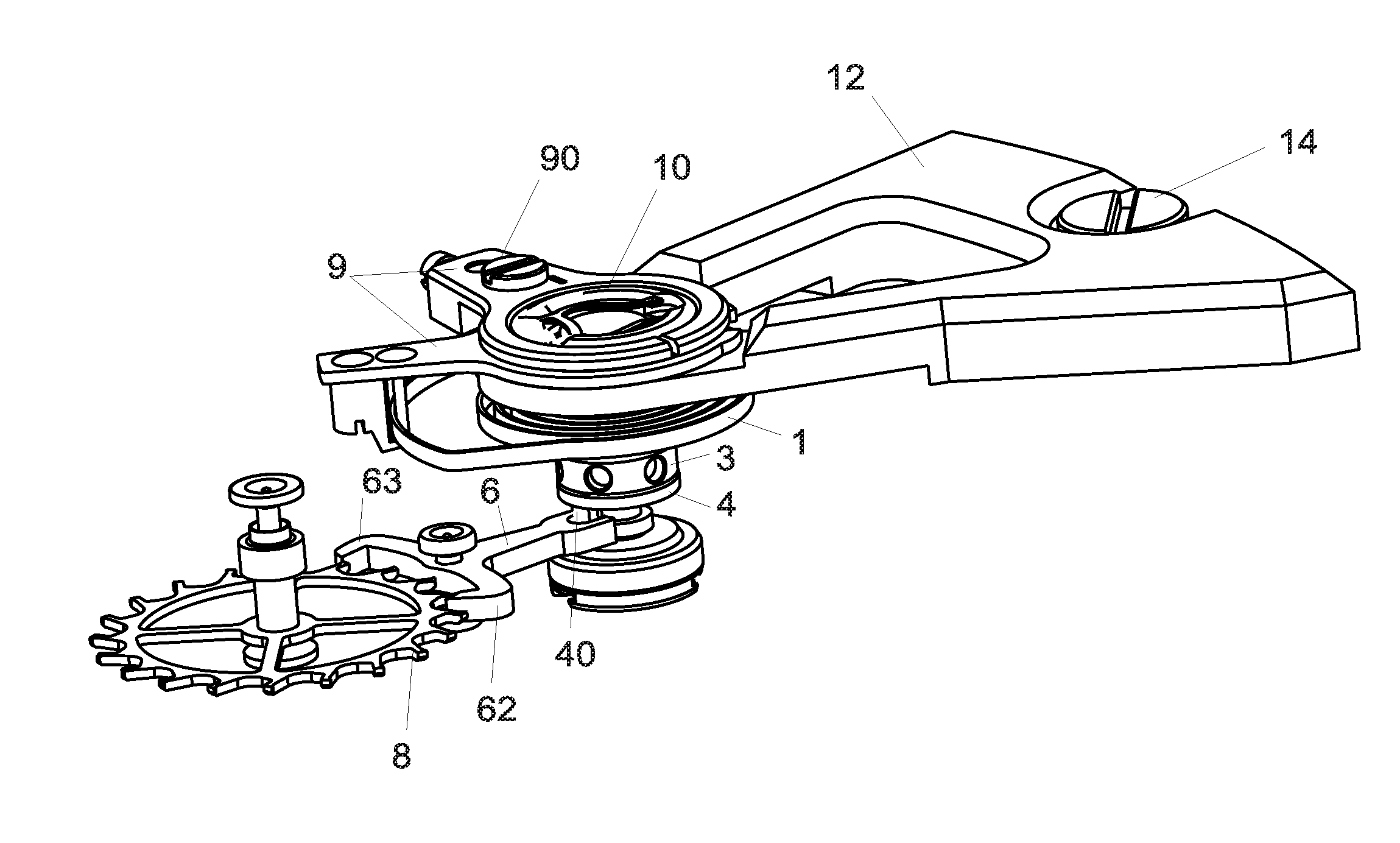
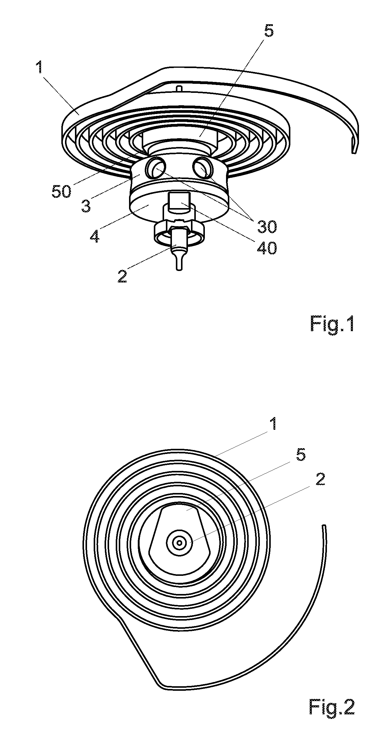
[0024]An embodiment of the regulator organ is illustrated in FIGS. 1 and 2. This regulator organ is designed in particular to serve as regulator for the chronograph function of a mechanical chronograph; a single movement can comprise two regulator organs on the same plate, or on two distinct plates, with one of the regulator organs serving to regulate the running of the watch whilst the other regulator organ, identical or similar to that described in this application, serves to regulate the running of the chronograph function. A distinct barrel supplies the energy necessary to each regulator organ, which allows disturbances in the running of the watch to be avoided when the chronograph is started.

[0025]The power reserve of the second barrel, which indicates the duration that can still be measured with the stopwatch before the second barrel needs to be recharged, is preferably indicated on the dial by means of a power reserve indicator of the chronograp...


PUM


Abstract

Mechanical watch movement comprising a mechanical chronograph with a regulator organ for regulating the running of the chronograph, characterized in that the regulator organ of the chronograph is placed in an imaginary circle (A) coaxial to the movement and having a radius (r1) smaller than 50% of the maximum outer radius of the movement.

Description

TECHNICAL FIELD[0001]The present invention concerns a mechanical watch movement having a mechanical chronograph with a regulator organ for regulating the running of the chronograph.STATE OF THE ART[0002]Mechanical watches usually comprise a regulator organ composed of an flywheel, called balance, on the axis of which a hairspring, called spiral, is fastened. The balance wheel and hairspring combination oscillates around its position of equilibrium at a frequency that depends notably on the rigidity of the spiral and on the moment of inertia of the balance.[0003]Known balances are constituted of an annular mass, the felloe, held by one or two arms. Taking into account the available energy, balances have a great moment of inertia for a low mass; this means that their diameter is as large as the available space allows and that the mass is concentrated at the periphery in the felloe. This moment of inertia can furthermore be modified to set the watch, either manually by means of screws,...

Claims


Application Information

Patent Timeline
IPC IPC(8): G04F7/00G04B15/00
CPCG04F7/0847G04F7/088G04B17/063G04B17/06G04B15/08G04F7/0895
Inventor SEMON, GUY
Owner LVMH SWISS MFG SA
Learn More