Centrifugal filter

a centrifugal filter and filter body technology, applied in the field of centrifugal filter, can solve the problems of inevitability of short circuit flow and decrease in separation efficiency, and achieve the effect of efficiently improving the separation efficiency of the filter and eliminating short circuit flow

Inactive Publication Date: 2012-09-27
GUANGDONG LIANSU TECH INDAL
View PDF3 Cites 1 Cited by
  • Summary
  • Abstract
  • Description
  • Claims
  • Application Information

AI Technical Summary

Benefits of technology

[0007]An object of the present invention is to provide a centrifugal sand filter that is efficient in sidewall short circuit flow elimination or reduction and has relatively high separation efficiency.

Problems solved by technology

Short circuit flow is inevitable in conventional sand filter due to the structure of the flow guiding device used therein.
In this case, coarser particles are present in the overflow where they are not supposed to be present, such that the separation efficiency is decreased.

Method used


Image

  • Centrifugal filter
  • Centrifugal filter
  • Centrifugal filter

Examples


example 1

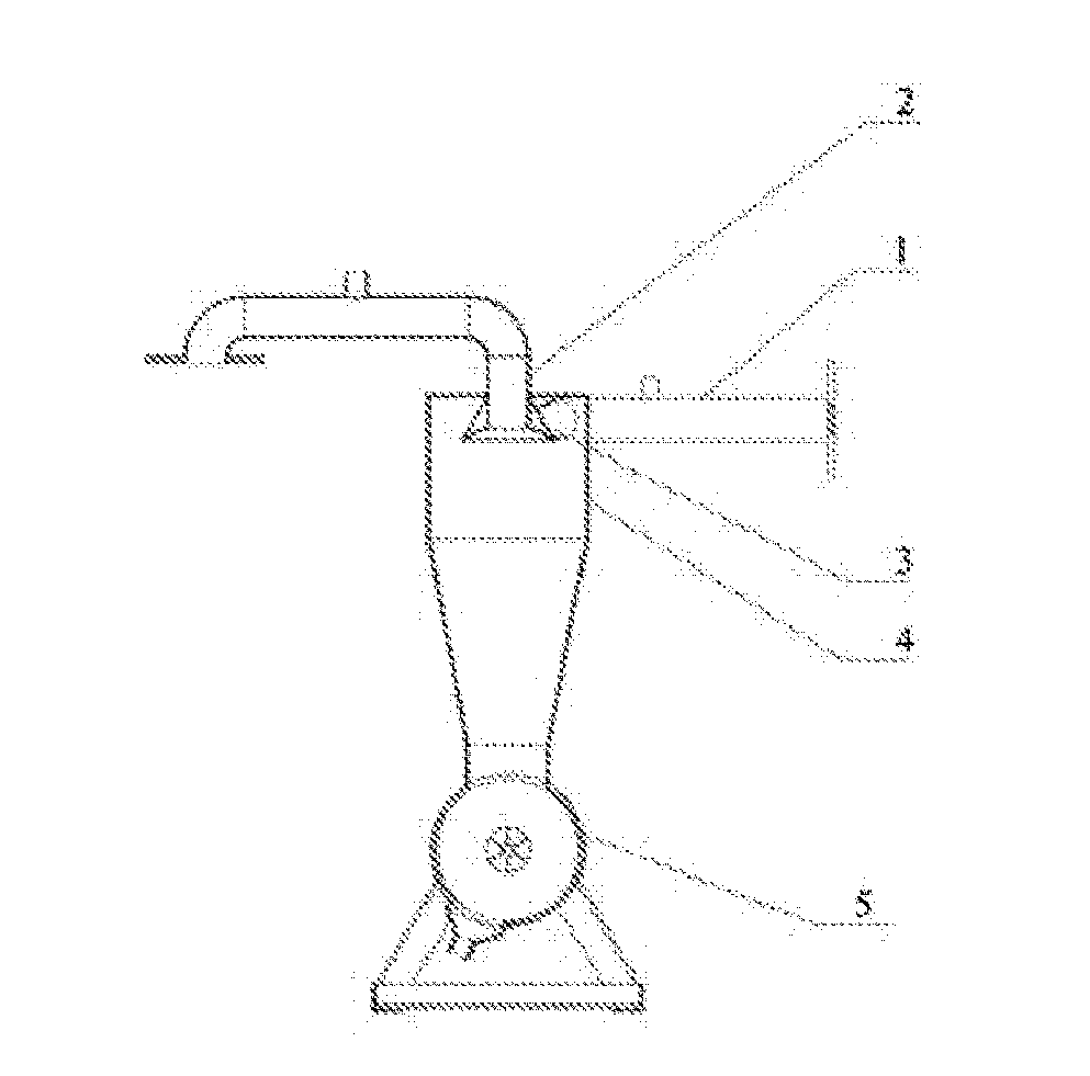
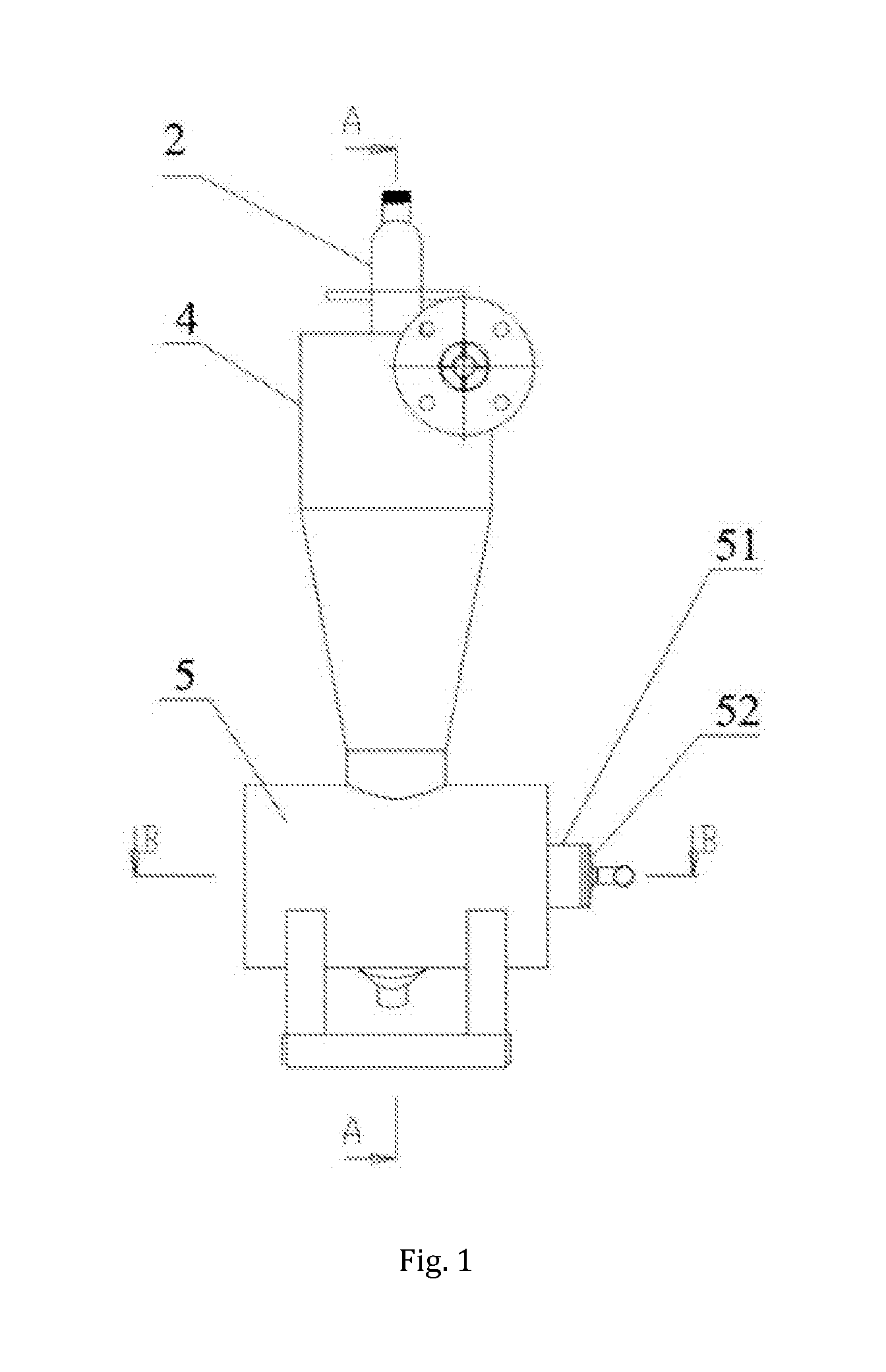
[0034]As shown in FIGS. 1 to 5, a centrifugal filter is provided which comprises a water inlet pipe 1, an overflow pipe 2, a flow guiding device 3, a filter body 4 with a cover, and a sedimentation container 5. The water inlet pipe 1 is mounted on the filter body 4 in tangential direction of the filter body 4. The sedimentation container 5 is in fluid communication with the bottom of the filter body 4. The overflow pipe 2 is disposed above the cover of the filter body 4 with the flow guiding device 3 disposed below the cover.

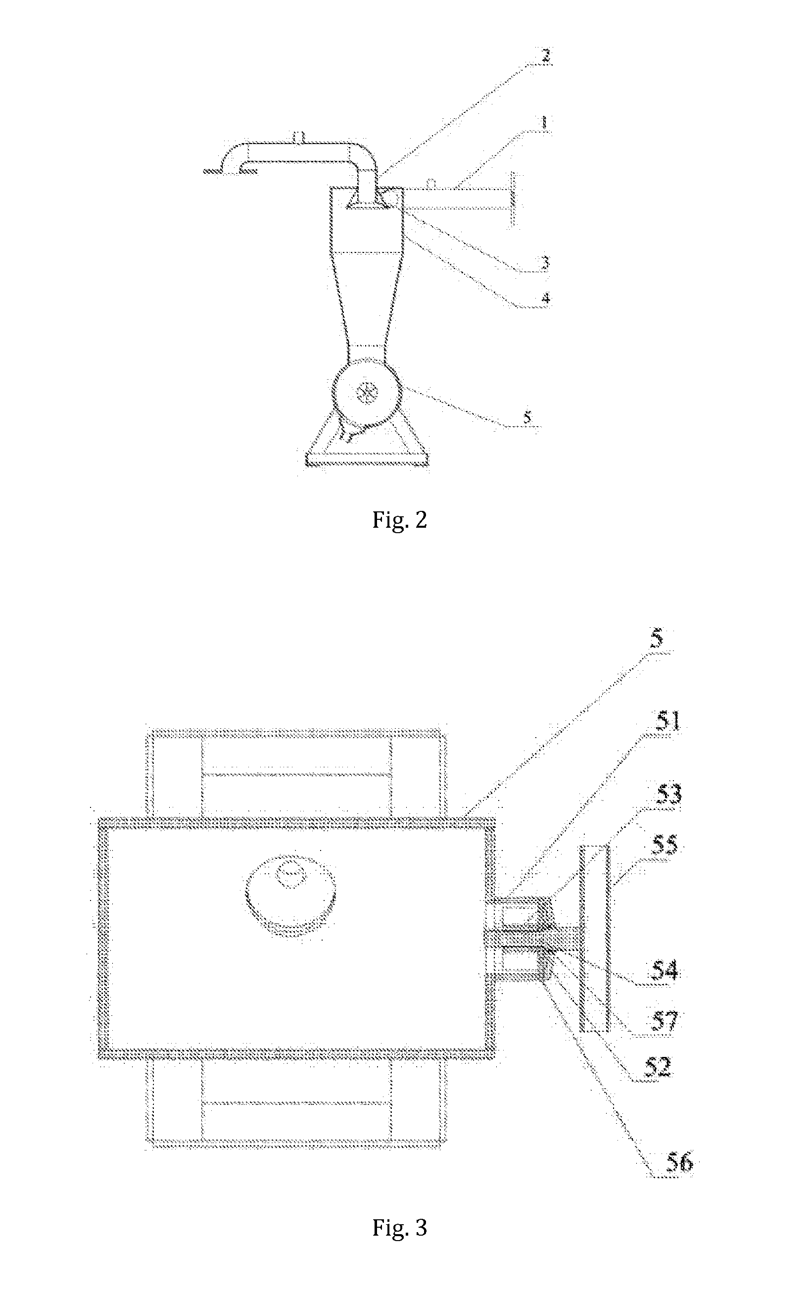
[0035]The flow guiding device 3 includes an inner cylinder 31, an upper conical body 32 and a lower conical body 33, with the cylinder 31 and the conical bodies 32, 33 coaxially disposed. The upper base of the inner cylinder 31 coincides with the small diameter base of the upper conical body 32, and the lower base of the inner cylinder 31 coincides with the small diameter base of the lower conical body 33. The inner diameter of the inner cylinder 31 equals to th...

example 2

[0042]The filter provided in example 2 is substantially similar to example 1 except that the lower conical body 33 is substituted with a circular plate 33. As shown in FIG. 6, the upper base of the inner cylinder 31 coincides with the small diameter base of the upper conical body 32, and the lower base of the inner cylinder 31 coincides with the inner circular surface of the lower conical body 33. The large diameter base of the upper conical body 32 coincides with the outer circular surface of the lower conical body 33.

[0043]The inner diameter of the inner cylinder 31 equals to the inner diameter of the overflow pipe 2, and the inner cylinder 31 is in fluid communication with the overflow pipe 2.

Examlpe 3

[0044]As shown in FIG. 7, the filter in this example differs from example 1 or 2 in that the outer surface 321 of the upper conical body 32 of the flow guiding device 3 is a curved surface, the generator of the outer surface 321 is thus a curved line.


PUM

PropertyMeasurementUnit
Diameteraaaaaaaaaa

Abstract

A centrifugal filter is provided comprising a water inlet pipe, an overflow pipe, a flow guiding device, a filter body with a cover, and a sedimentation container. The water inlet pipe is mounted on the filter body in tangential direction of the filter body, and the sedimentation container is in fluid communication with the bottom of the filter body. The overflow pipe is disposed above the cover of the filter body with the flow guiding device disposed below the cover, and the flow guiding device is in fluid communication with the overflow pipe. The incoming water from the inlet pipe enters into the filter along the sidewall of the filter body in tangential direction, so that the incoming water rotates around the conical outer surface of the flow guiding device and moves downwards, thus the rotational radius of the water stream is increased. A rotation momentum around the axis of the filter body is generated to generate centrifugal force to separate solid particles from the water stream. A momentum toward away from the axis of the filter body is generated to eliminate short circuit flows and overcome separation efficiency decrease problems caused by the short circuit flows.

Description

TECHNICAL FIELD [0001]The present invention relates to an irrigation device in agriculture, and in particular, to a centrifugal filter.TECHNICAL BACKGROUND[0002]Centrifugal filters are widely used in agricultural irrigation. For example, China patent No. 98240446.8 discloses a combined filter which comprises a filter tube upon which is mounted a flow guiding device. The flow guiding device is capped by a cover at the top and provided with an outlet at one side with a pressure meter connector disposed thereon. In the flow guiding device, there is disposed a mesh in the shape of a filter body.[0003]Short circuit flow is one of the main characteristic stream flows in the filter of this type, which is a key factor causing coarse particles existing in overflow and fine particles existing in separated residues. Short circuit flow is inevitable in conventional sand filter due to the structure of the flow guiding device used therein. The separation efficiency, flow capacity and energy loss ...

Claims


Application Information

Patent Timeline
IPC IPC(8): B01D29/88
CPCB01D21/0042B01D21/0087B04C5/185B01D21/267B04C5/13B01D21/245
Inventor YANG, JIYUEHUANG, HONGBINFU, WEIQUAN
Owner GUANGDONG LIANSU TECH INDAL
Why Eureka
Try Eureka