Prefilled syringe with a limited-withdrawal plunger rod

a technology of syringe and plunger, which is applied in the field of syringe, can solve the problems of limited withdrawal of plunger, and achieve the effect of preventing the withdrawal of the plunger

Inactive Publication Date: 2012-09-13
KYOWA HAKKO KIRIN CO LTD +1
View PDF8 Cites 13 Cited by
  • Summary
  • Abstract
  • Description
  • Claims
  • Application Information

AI Technical Summary

Benefits of technology

[0006]The invention provides the prefilled syringe comprising a barrel having a closed front-end wall with a small passageway through which injection liquid is discharged and a rear opening, a plunger including a sliding plug liquid-tightly contacting with the inner surface of the barrel and partitioning the inside of the barrel into a liquid-filled area which is formed between the plunger and the closed front-end wall and in which injection liquid is filled and sealed and a liquid-unfilled area in the back of the liquid-filled area and a plunger rod extending backward from the sliding plug through the rear opening of the barrel, and a plunger withdrawal-limiting member fixed to the barrel, which limits withdrawal of the plunger by engaging the plunger and prevents injection liquid from contacting with the surface of the liquid-unfilled area in the barrel.
[0010]In other form of embodiment, the withdrawal-limiting member may be made in the form of a cylindrical member in which a male screw is provided on the outer peripheral surface thereof, and on the other hand, the plunger withdrawal-limiting member may be formed in the form of an annular flange in which the inner peripheral surface of the flange defines an opening having a size corresponding to the plunger withdrawal-limiting member, the annular flange being provided at the rear end opening of the barrel and extending inwardly in a radial direction from the peripheral edge of the opening and a female screw to be mated with the male screw is formed on the inner peripheral surface of the flange. In this form of syringe, when the plunger is withdrawn for a predetermined distance over a predetermined position, the stopper member engages the withdrawal-limiting member, thus preventing withdrawal of the plunger. If the male screw of the stopper member is further turned and fitted into the female screw on the plunger withdrawal-limiting member the plunger can be further withdrawn.

Problems solved by technology

As a result of this, withdrawal of the plunger is limited by engagement of the stopper member with the withdrawal-limiting flange.

Method used


Image

  • Prefilled syringe with a limited-withdrawal plunger rod
  • Prefilled syringe with a limited-withdrawal plunger rod
  • Prefilled syringe with a limited-withdrawal plunger rod

Examples


Embodiment Construction

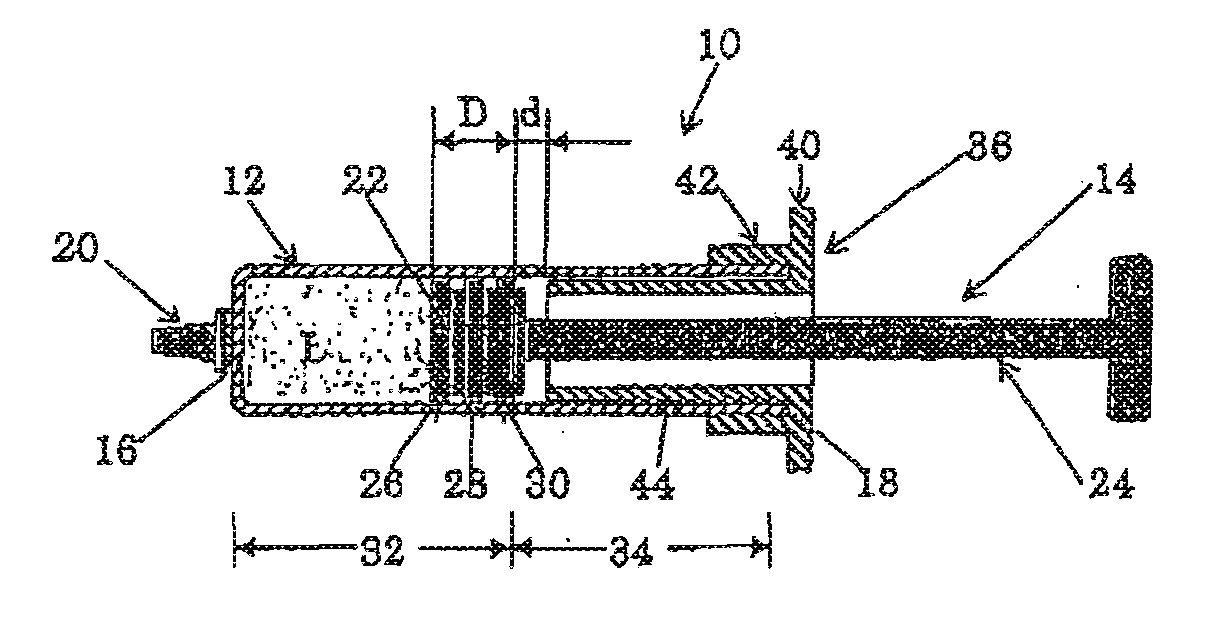
[0019]The mode for carrying out the prefilled syringe according to the invention is explained below, referring to the attached drawings.

[0020]FIG. 1 shows the first mode for carrying out the prefilled syringe 10 according to the invention. As illustrated, the prefilled syringe 10 has a barrel 12 in a cylindrical form and the plunger 14 to be inserted into the barrel. The barrel has the front-end wall 16, the tip of which has a small passageway (not shown in the FIG. 1) through which the injection liquid is discharged, and the rear opening 18 through which the plunger 14 is received. A barrel tip cover 20 is mounted on the outer surface of the tip of the front-end wall 16. The plunger 14 has a sliding plug 22 at its tip which is able to slidably move along the inner surface of the barrel 12 and a plunger rod 24 which extends outwardly from the sliding plug 22 to the outside of the barrel through the rear opening 18 at the rear end of the barrel. FIG. 1 shows the completed prefilled s...


PUM


Abstract

A risk of injection liquid contamination due to contact of injection liquid in an injection-liquid filled area in a barrel with the surface in an injection-liquid unfilled area in the barrel by causing a plunger of a prefilled syringe to be inadvertently withdrawn by mishandling which may leads to medical malpractice, is eliminated by the invention. Withdrawal of a plunger 14 is limited by engagement of a barrel 12 in which a withdrawal-limiting member 48 is provided and a the plunger 14 in which a withdrawal-limiting member 54 is provided. As a result of this, contact of the injection liquid L prefilled to a liquid-filled area 32 in the barrel 12 with the surface of a liquid-unfilled area 34 in the barrel by withdrawal of the plunger 14 is prevented.

Description

TECHNICAL FIELD[0001]The present invention relates to a syringe in which injection liquid is prefilled (prefilled syringe), and more particularly, the prefilled syringe which is provided with a means for preventing contamination of the prefilled injection liquid.BACKGROUND TECHNIQUE[0002]For a conventional type of prefilled syringe, injection liquid is filled into the syringe barrel and a sliding plug (of the liquid-injecting plunger) is inserted in the barrel, usually under a sterilized condition, and thereafter, a plunger rod is fixed to the sliding plug and works such as labeling and packaging are done for shipment under a non-sterilized condition.[0003]A syringe in which some specific injection liquid is prefilled may be finally sterilized by heating using an autoclave etc. after packaging. However, in other type of syringe in which injection liquid unable to be sterilized by heating is prefilled, bacteria or other microorganisms are considered to have started to adhere to the s...

Claims


Application Information

Patent Timeline
Patent Type & Authority Applications(United States)
IPC IPC(8): A61M5/315A61M5/31A61M5/28
CPCA61M5/31505A61M2005/3117A61M5/31501A61M2005/31506A61M2005/31508A61M2005/3139A61M5/315A61M5/178A61M5/28
Inventor HATO, SEIICHI
Owner KYOWA HAKKO KIRIN CO LTD
Why Eureka
Try Eureka