
Adaptive hydrokinetic energy harvesting system

Active Publication Date: 2012-09-13
LYNCH GERARD J
View PDF27 Cites 18 Cited by
  • Summary
  • Abstract
  • Description
  • Claims
  • Application Information

AI Technical Summary

Benefits of technology

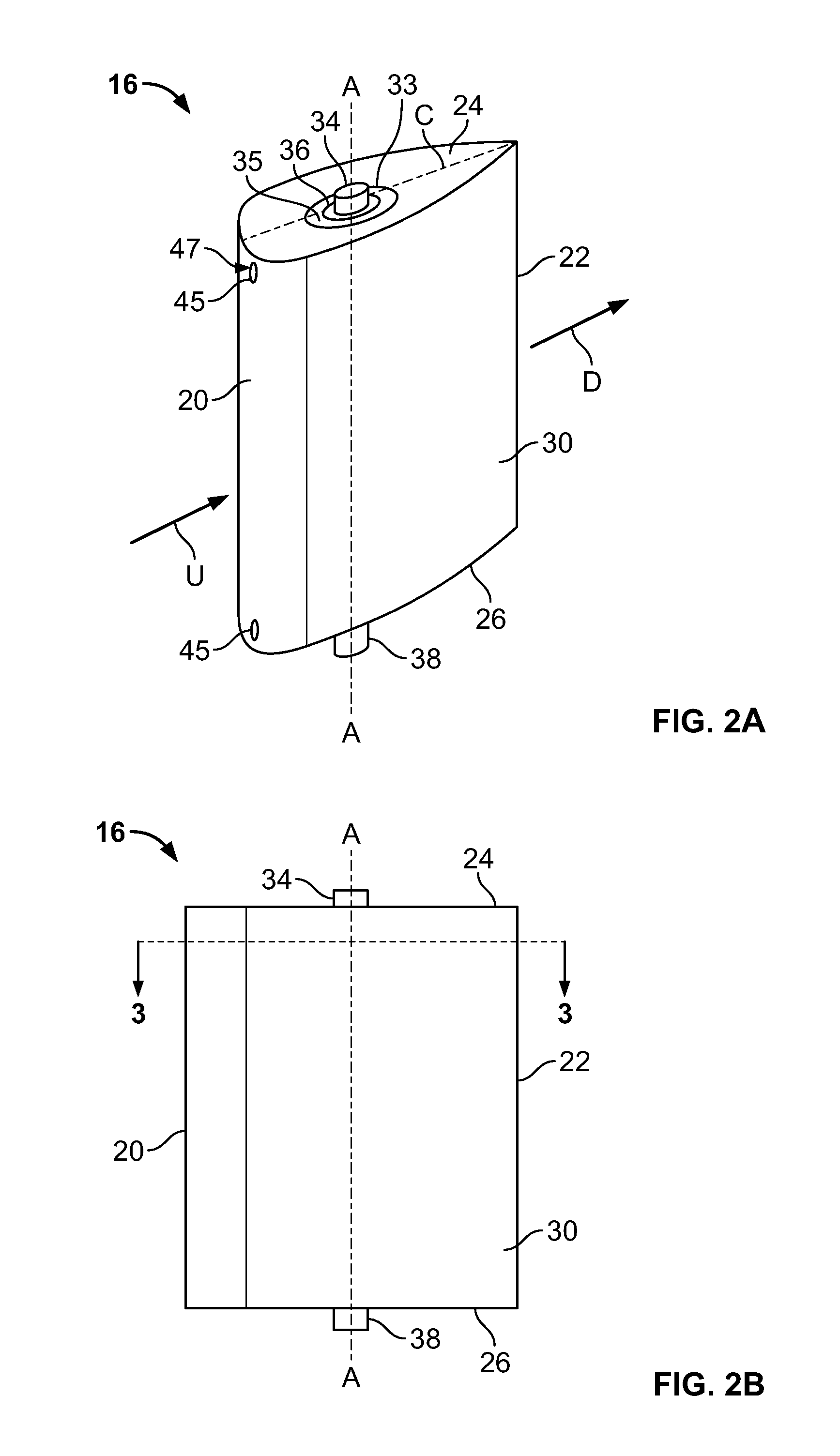
[0004]In one aspect, the present invention provides an system for harvesting hydrokinetic energy from a flowing fluid which adapts to changes in the flow characteristics. In some embodiments of the present invention, the system includes a supporting structure that defines a flow-way therethrough, and at least one vane having a hydrofoil cross-section with a leading edge for facing into the direction of flow of a flowing fluid and a trailing edge opposite the leading edge. The vane is positioned within the flow-way and mounted to said supporting structure so that it oscillates as the fluid flows across it from the leading edge to the trailing edge, thereby generating torque. The vane is also attached to an energy conversion module that converts the torque to an electrical current. The energy conversion module includes an electrical power generator connected to the vane such that the oscillating vane drives the generator. The system also includes a control module that measures the oscillation of the vane, the generated torque, or the characteristics of the generated current, and modifies the resistance of the vane or the conversion of the electrical current accordingly.

Problems solved by technology

A hydrokinetic electrical generating system that is scalable in size and is adaptive to changing fluid flow conditions for maintaining and maximizing energy harvesting efficiencies is needed, but has yet to be provided.

Method used


Image

  • Adaptive hydrokinetic energy harvesting system
  • Adaptive hydrokinetic energy harvesting system
  • Adaptive hydrokinetic energy harvesting system

Examples


Embodiment Construction

[0033]Although the present invention can be used in conjunction with many types of fluid, such as water, fuel, oil, industrial effluent, air, gas, etc., it is particularly suitable for use in connection with hydrodynamic fluid flow. Accordingly, the present invention will be described hereinafter in connection with hydrodynamic fluid flow. It should be understood, however, that the following description is only meant to be illustrative of the present invention and is not meant to limit the scope of the present invention, which has applicability to other fluids.

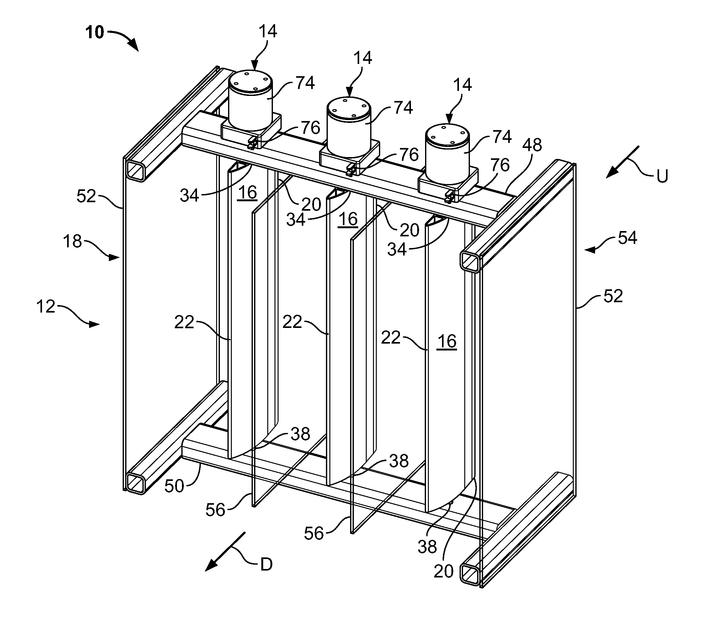
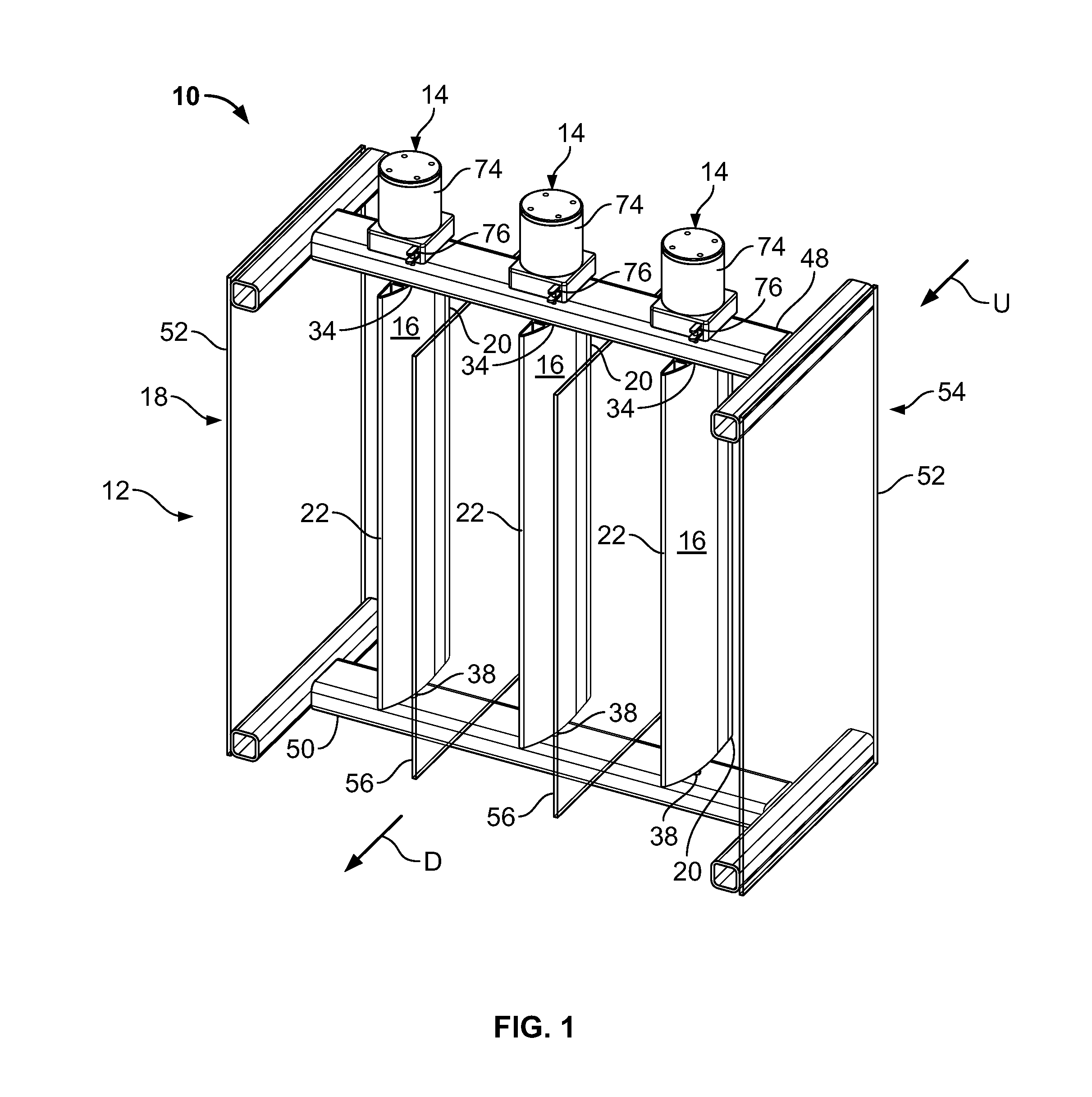
[0034]FIG. 1 illustrates an adaptive hydrokinetic energy harvesting system (hereinafter “the system 10”) that features an energy extraction unit 12 which is interconnected with one or more energy conversion and control units 14 through vanes 16 having hydrofoil contours. The energy extraction unit 12 extracts hydrokinetic energy from fluid flowing through it. The energy conversion and control unit 14 maximizes the functional e...


PUM


Abstract

An adaptive system for harvesting hydrokinetic energy from flowing fluid uses a hydrofoil-type vane in a flow-way and an electrical power generator to convert torque generated by the oscillating vane to electrical current. The generator may be electromagnetic or piezoelectric. The system includes a control module that measures the oscillation of the vane, the generated torque, or the characteristics of the generated current, and modifies the resistance of the vane or the conversion of the electrical current in response to changes therein. Some systems include a frame that can be anchored in a body of water. Some systems are portable and provide illumination. Some systems are adapted for use as hiking or camping gear and may be inserted into stream beds or used as walking sticks. Some systems are in-line devices. Some systems are adapted as fishing lures.

Description

CROSS-REFERENCE TO RELATED APPLICATIONS[0001]This application claims the benefit of U.S. Provisional Patent Application Ser. No. 61 / 450,270, filed Mar. 8, 2011, the disclosure of which is incorporated by reference herein in its entirety.FIELD OF THE INVENTION[0002]The present invention relates to a fluid energy harvesting system, and, more particularly, to a hydrokinetic energy harvesting system that is adaptive to changing hydrodynamic conditions to maximize energy harvesting efficiency.BACKGROUND OF THE INVENTION[0003]The economical generation of electrical power has long been an important humanitarian objective. More recently, the generation of electrical power in an environmentally-friendly manner has also become an important objective. Hydrokinetic generating systems have been provided to harvest renewable energy to meet these objectives. A hydrokinetic electrical generating system that is scalable in size and is adaptive to changing fluid flow conditions for maintaining and ma...

Claims


Application Information

Patent Timeline
Patent Type & Authority Applications(United States)
IPC IPC(8): F03B13/10H02N2/18F21L13/00H02P9/04
CPCF03B17/06F03D5/00H02N2/181Y02E10/70H02P9/04Y02E10/28H02N2/185Y02E10/20F03B1/04F03B13/10F03B15/16
Inventor LYNCH, GERARD J.
Owner LYNCH GERARD J
Learn More