
Device and method for creation of a hydraulic jump, notably a fountain or swimming pool

a technology of hydraulic jumps and devices, which is applied in the direction of water supply installation, gas/liquid distribution and storage, application, etc., can solve the problems of inability to adjust the parameters of the jump, the flow rate and the falling height required to produce a sufficient load in the liquid or a jump of notable size must be completely excessive, and the shape of the jump is often unstabl

Inactive Publication Date: 2012-09-13
COMMISSARIAT A LENERGIE ATOMIQUE ET AUX ENERGIES ALTERNATIVES
View PDF3 Cites 2 Cited by
  • Summary
  • Abstract
  • Description
  • Claims
  • Application Information

AI Technical Summary

Benefits of technology

[0008]The use of the invention will, conversely, enable hydraulic jumps having desired characteristics of shape, dimensions and stability to be obtained easily, and enable these characteristics to be adjusted easily, notably in such a way as to change their shape, changing from a regular shape, circular for example, to an irregular shape, polygonal for example, or vice versa, and from a stable jump to an unstable jump, or vice versa.
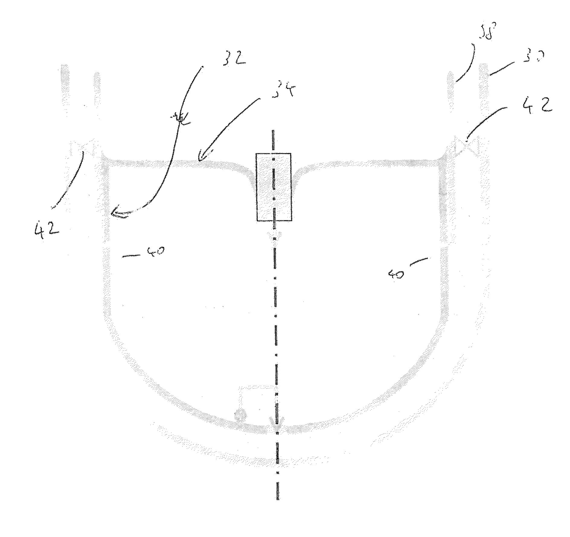
[0010]Typically, the device allows the a convergent circulation of the fluid to be established, from the inlet region to the outlet region.
[0011]It is frequently the case that the device is annular, the fluid outlet region being surrounded by the inlet region, and both being circular: the jump is then a circular line. This definition must, however, not be understood too strictly, since regions with irregular circle shapes, elliptical shapes for example, give comparable results, as do regions which are not closed, but which extend only over parts of circles, for example: the characteristic which it is desirable to establish is a convergent flow, favouring the creation of a jump of notable height, over a region of small width, or a width which is much smaller than the width of the fluid inlet region, with options of adjusting the characteristics of the jump more easily.

Problems solved by technology

Such devices and methods seem practicable only on a very small scale; otherwise the flow rate and falling height required to produce a sufficient load in the liquid or a jump of notable size would have to be completely excessive.
Nor do they lend themselves to an adjustment of the parameters of the jump.
It was, however, observed that these shapes were often unstable, and that they also depended on the surface tension of the liquid, which limits these phenomena to installations of roughly one centimetre in size.
It is, furthermore, manifest that such devices with nozzles do not easily lend themselves to adjustments of the conditions of the flow and of the parameters of the jump.

Method used


Image

  • Device and method for creation of a hydraulic jump, notably a fountain or swimming pool
  • Device and method for creation of a hydraulic jump, notably a fountain or swimming pool
  • Device and method for creation of a hydraulic jump, notably a fountain or swimming pool

Examples


Embodiment Construction

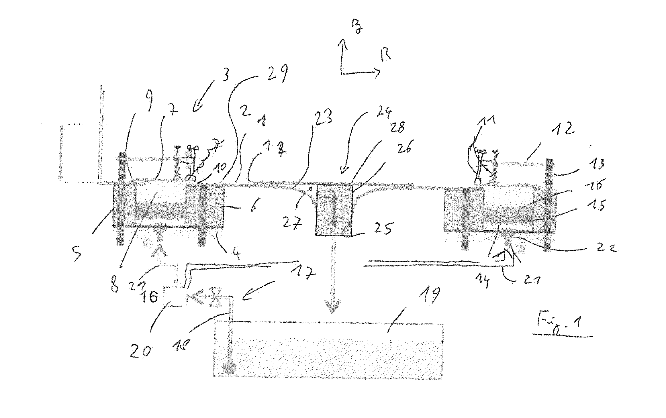
[0031]A first embodiment is represented in FIG. 1. The device is seen as a diametral section, and is circular in shape. It consists of four main elements, namely a liquid, an element through which the liquid enters, a surface over which the liquid flows, and an element for draining the liquid. Optional elements are a tank of the liquid, a liquid distribution circuit and a pump. The liquid flows from the injection element to the drainage element over the flow surface forming a jump (1), i.e. a sudden rise in the level of the free surface (2).

[0032]The inlet element (3) includes a bottom (4), concentric walls (5 and 6), and an upper plate (7), which demarcate a circular trench (8) occupied by the liquid. The upper plate (7) is attached to the outer wall (5) in watertight fashion by a silicon joint (9). It extends slightly above the inner wall (6) forming a circular slit (10). It is deformable and can be pressed downwards by rotating a number of threaded rods (11) held in place in capt...


PUM


Abstract

A hydraulic jump (1) is created at the free surface (2) of a liquid subjected to a flow over a surface (23) which declines towards a liquid outlet region, and where the supply is made by the overflow of a supply system (3), and where an element (24) rises above the flow surface (23) to form a retention volume (27) of the liquid before it is drained. The liquid may be recycled. The jump (1) may or may not be stable. The invention may be applied to the creation of artificial waves for simulation devices, ornamental fountains or swimming pools.

Description

TECHNICAL FIELD[0001]The subject of this invention is a device and method for creation of a hydraulic jump; or again, more generally, for creation of a fluid jump, since the jump phenomenon is not restricted to liquids, and can be applied also to heavy gases in a lighter atmosphere. The device could then be for decorative use, such as simulations of waves, or scientific use, for performing certain experiments. Fountains and swimming pools may be cited as tangible applications.[0002]A hydraulic jump is a sudden variation of the level of the free surface of a liquid (or of a gas). It is a sudden transition from a high-speed flow characteristics to subcritical characteristics.GENERAL ACCOUNT OF THE INVENTION[0003]The invention enables such a jump to be created with a very simple device.[0004]Particular objects of the invention are the management of settings which enable the characteristics of the jump to be regulated, and also particular means contributing to favourable embodiments of ...

Claims


Application Information

Patent Timeline
IPC IPC(8): B05B17/08E04H4/14F15D1/00
CPCB05B17/08F15D1/00E04H4/0006Y10T137/0318Y10T137/8593
Inventor FOGLIZZO, THIERRY
Owner COMMISSARIAT A LENERGIE ATOMIQUE ET AUX ENERGIES ALTERNATIVES
Learn More