
Rolling Chip Conveyor

a conveyor and chip technology, applied in the direction of cleaning process and equipment, solid separation, cleaning using liquids, etc., can solve the problems of high cost and time consumption of removing chips, and achieve the effect of removing rough chips and eliminating fine chips

Inactive Publication Date: 2012-09-13
CHUNG YI HAO
View PDF5 Cites 4 Cited by
  • Summary
  • Abstract
  • Description
  • Claims
  • Application Information

AI Technical Summary

Benefits of technology

[0008]Another object of the present invention is to provide a rolling chip conveyor that is used to scrape the rough and the fine chips, and produced at a lower cost.
[0010]a body including a lower segment, a tilted segment, and an upper segment, two ends of the tilted segment connecting with the lower segment and the upper segment respectively, and the upper segment including a first outlet to eliminate rough chips outside, a second outlet to eliminate fine chips, and a driving device, the second outlet being fixed on the body and facing downward, and the first outlet being disposed on one side of the upper segment;

Problems solved by technology

However, such a conventional chip conveyor have to eliminate chips by using the removing plate and a scraping piece additionally, thus eliminating chips at a high cost and consuming time.

Method used


Image

  • Rolling Chip Conveyor
  • Rolling Chip Conveyor
  • Rolling Chip Conveyor

Examples


Embodiment Construction

[0024]The present invention will be clearer from the following description when viewed together with the accompanying drawings, which show, for purpose of illustrations only, the preferred embodiment in accordance with the present invention.

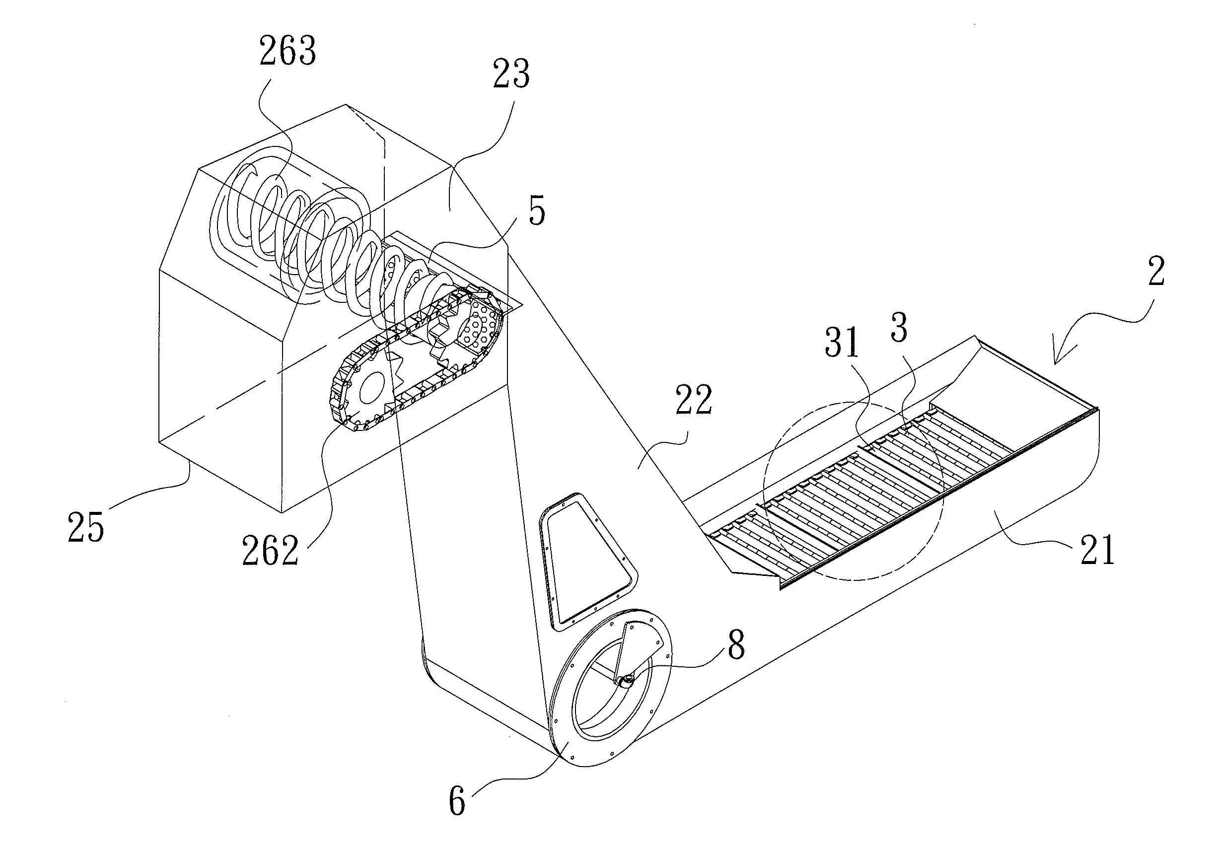
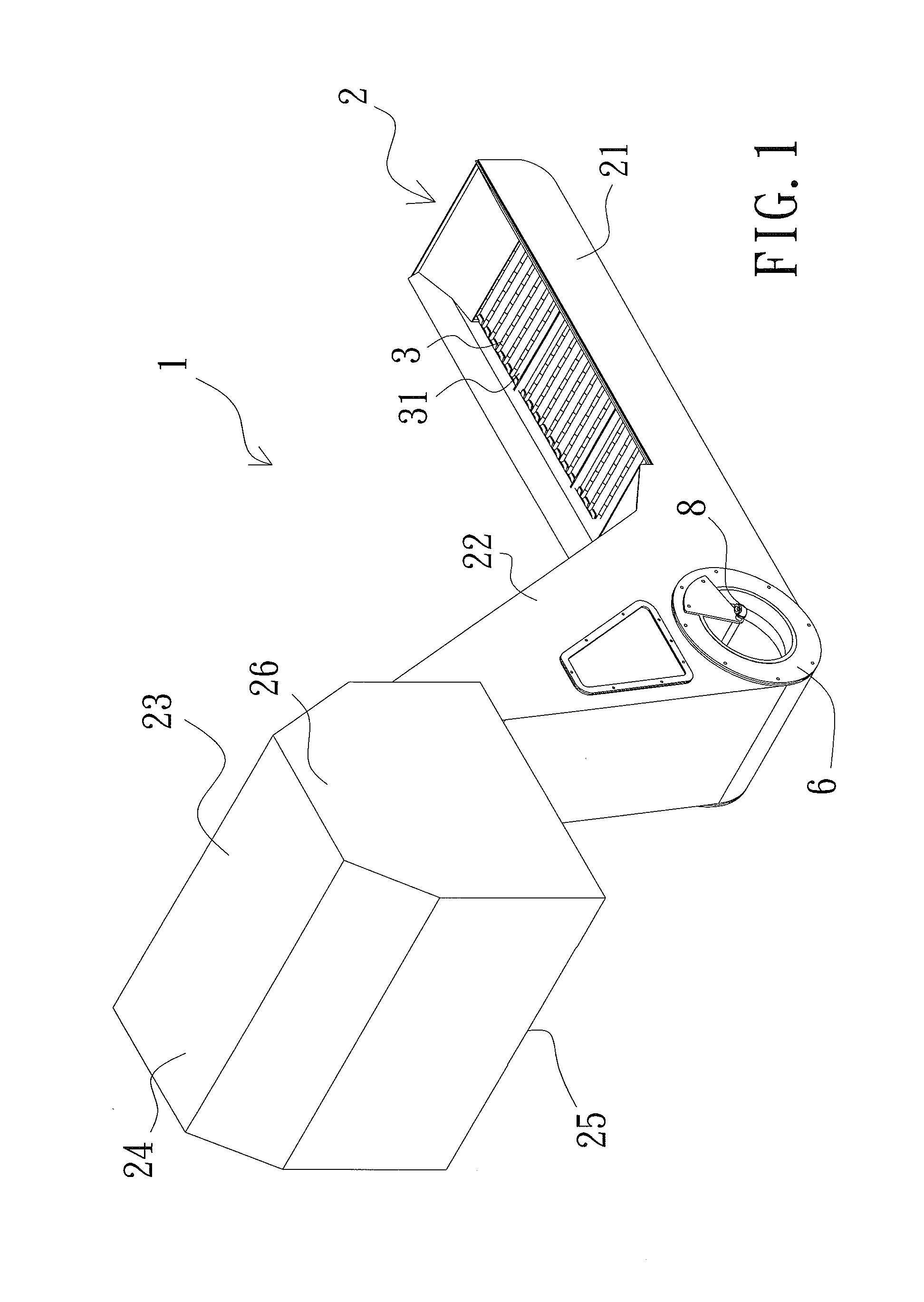
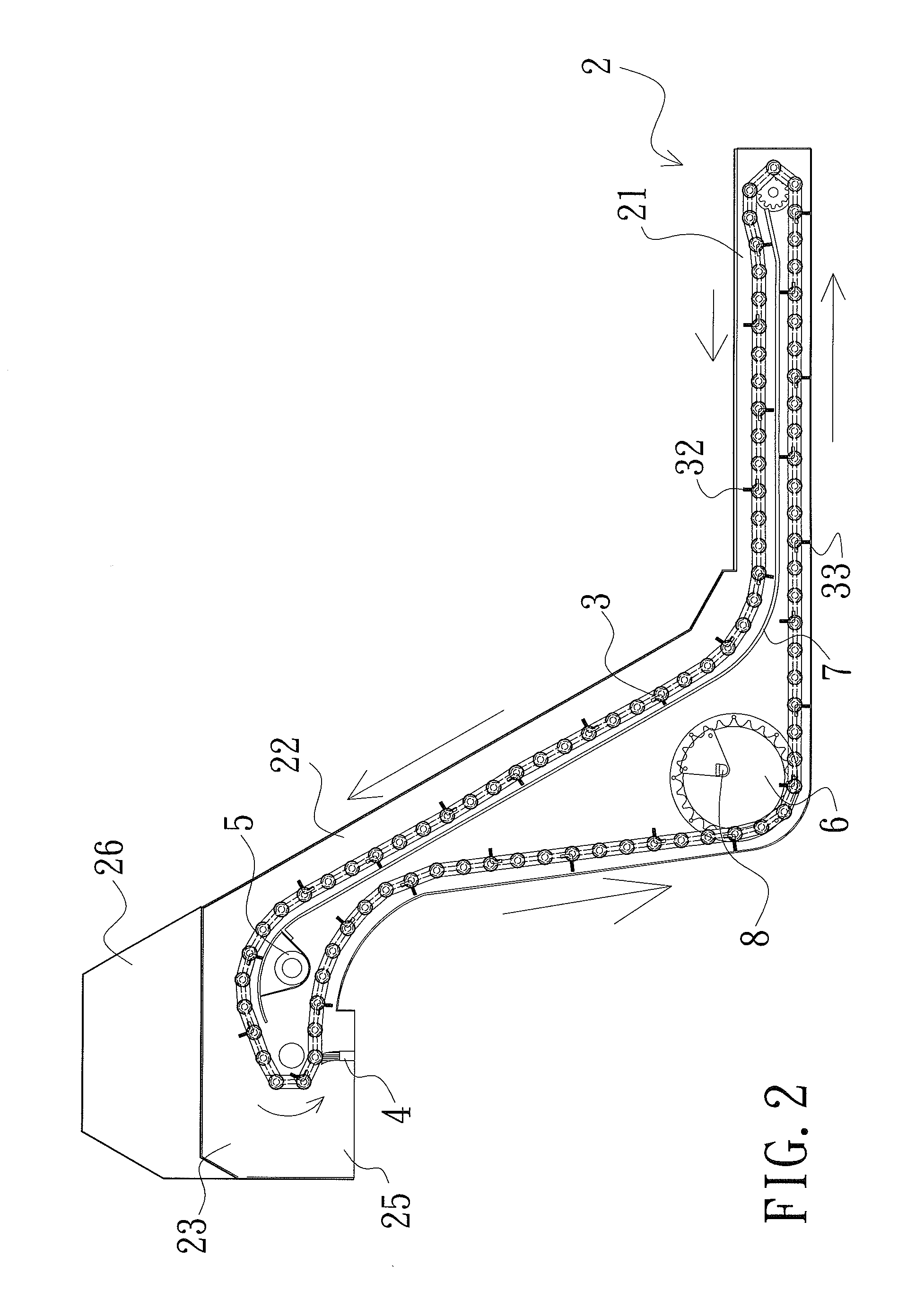
[0025]With reference to FIGS. 1-9, a rolling chip conveyor 1 according to a preferred embodiment of the present invention comprises a body 2, a tracking belt 3, a scraper 4, a first filter 5, and a second roller 6.

[0026]The body 2 includes a lower segment 21, a tilted segment 22, and an upper segment 23, wherein two ends of the tilted segment 22 connect with the lower segment 21 and the upper segment 23 respectively, and the upper segment 23 includes a first outlet 24 to eliminate rough chips outside, a second outlet 25 to eliminate fine chips, and a driving device 26; the second outlet 25 is fixed on the body 2 and faces downward, and the first outlet 24 is disposed on one side of the upper segment 23.

[0027]The driving device 26 includes a motor...


PUM


Abstract

A rolling chip conveyor contains a body including a lower segment, a tilted segment, and an upper segment, two ends of the tilted segment connecting with the lower segment and the upper segment respectively, the upper segment including a first outlet to eliminate rough chips outside, a second outlet to eliminate fine chips, and a driving device, the second outlet being fixed on the body and facing downward, the first outlet being disposed on one side of the upper segment; a tracking belt arranged in the body to correspond to the lower segment, the tilted segment, and the upper segment, engaging with and being actuated by the driving device, the tracking belt including al least one hole; a scraper disposed proximate to the second outlet and contacting with the tracking belt; a first filter corresponding to the first outlet and beings fixed around an inner side of the tracking belt.

Description

BACKGROUND OF THE INVENTION[0001]1. Field of the Invention[0002]The present invention relates to a chip conveyor, and more particularly to a rolling chip conveyor.[0003]2. Description of the Prior Art[0004]A conventional chip conveyor contains a body including a tilted surface formed thereon at a proper angle, an outlet to eliminate chip extending outward from the tilted surface, a transmitting mechanism fixed above the outlet to actuate a tracking belt, and a removing plate secured on the tracking belt to eliminate rough chips on a bottom end of the body, the rough chips are further conveyed toward the outlet from the tilted surface.[0005]However, such a conventional chip conveyor have to eliminate chips by using the removing plate and a scraping piece additionally, thus eliminating chips at a high cost and consuming time.[0006]The present invention has arisen to mitigate and / or obviate the afore-described disadvantages.SUMMARY OF THE INVENTION[0007]The primary object of the presen...

Claims


Application Information

Patent Timeline
Patent Type & Authority Applications(United States)
IPC IPC(8): B65G47/46B65G45/12
CPCB65G45/22B08B3/022B07B13/16B07B1/00
Inventor CHUNG, YI-HAO
Owner CHUNG YI HAO
Learn More